9
$\begingroup$

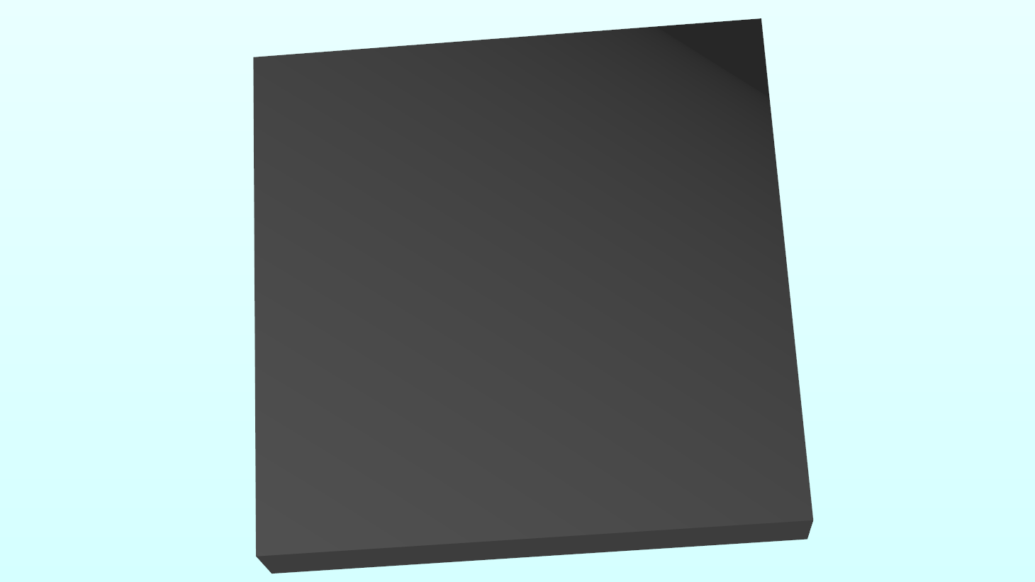
I use Phong shading as my lighting model. Nevertheless, the specular shading produces gradients in the light cone:

enter image description here

Hopefully you can see the gradient starting from the lower left corner expanding along the cuboid.

Here is the shader code that produces this specular light:

vec3 viewDir = normalize(-FragPos);
vec3 lightDir = normalize(-light.direction);
vec3 reflectDir = reflect(-lightDir, normal);
float spec = pow(max(dot(viewDir, reflectDir), 0.0), material.shininess);

By the way, I'm doing my lighting calculations in view-space.

Is there any chance to make the lighting smoother?

$\endgroup$
4
  • $\begingroup$ When you say "gradients", do you mean visible discontinuities in the colour? I'm assuming you don't want flat colour, but a smooth gradient with no bands visible? $\endgroup$ Commented Sep 7, 2016 at 20:53
  • $\begingroup$ That is exactly what I want. $\endgroup$
    – enne87
    Commented Sep 7, 2016 at 20:59
  • $\begingroup$ Are you passing lightDir is in viewspace in this case? $\endgroup$ Commented Sep 10, 2016 at 0:49
  • $\begingroup$ Yes, I do lighting in view-space. $\endgroup$
    – enne87
    Commented Sep 10, 2016 at 10:03

1 Answer 1

10
$\begingroup$

This is a common problem with very subtle gradients. The problem is that the image is displayed with 8 bits per component and this is not quite enough precision to make a gradient that is smooth to the eye under these conditions.

However, the underlying calculations being done in the shader are at higher precision (e.g. float = 24 effective bits of mantissa), so you can apply dithering to improve the appearance of the image.

You can do this by adding a slight amount of random noise to the value of each pixel in the shader. The noise can come from a texture, filled with random grayscale values in [0, 1] and mapped 1:1 to screen pixels. In the shader you remap this to the range [−0.5/255, 0.5/255] and add it to the output color.

Here's a Shadertoy demonstrating this. The left side has no dithering; the right side uses the procedure just described. As you can see, the banding vanishes on the right.

banding on left; dithered on right

Dithering effectively allows you to represent intermediate values between 8-bit integer levels. For instance, an area that the shader computes as 82.3 (out of 255) would normally be uniformly rounded down to 82, but with dithering it will come out as a random mix with 70% of the pixels set to 82, and 30% set to 83. The eye averages over this very slight, high-frequency noise and it becomes practically invisible.
$\endgroup$
5
  • $\begingroup$ Nice trick. I noticed you're adding .5 to pixel coordinates in the Shadertoy, is this to hit pixel centres in the texture rather than lerped samples? $\endgroup$
    – russ
    Commented Sep 8, 2016 at 6:23
  • 2
    $\begingroup$ @russ Hmm, I actually copy-pasted that bit from another Shadertoy. :D On a second look, I think that .5 is actually not needed; fragCoord should be on pixel centers already. $\endgroup$ Commented Sep 8, 2016 at 6:28
  • 3
    $\begingroup$ For anyone interested, here is also a well described article how to implement dithering to avoid color banding. Happy coding! $\endgroup$
    – enne87
    Commented Sep 9, 2016 at 14:38
  • $\begingroup$ you can try to perform actual statistics error distribution instead of just add noise uniformly, for an even better result. tannerhelland.com/4660/dithering-eleven-algorithms-source-code $\endgroup$
    – v.oddou
    Commented Apr 25, 2018 at 7:38
  • $\begingroup$ @v.oddou Maybe. Error diffusion would require an extra fullscreen pass, I think, versus adding noise which can be done inline in a shader. $\endgroup$ Commented Apr 25, 2018 at 15:55

Your Answer

By clicking “Post Your Answer”, you agree to our terms of service and acknowledge you have read our privacy policy.

Not the answer you're looking for? Browse other questions tagged or ask your own question.