8
$\begingroup$

I have some experience programming geometry and compute shaders - but never adventured myself in really playing with the fragment shaders. Currently, I am trying to better understand how they work and their potential. One of the things I have read in multiple places is that a fragment (i.e. a screen pixel) cannot extend beyond itself within the fragment shader. Which means, a given fragment being iterated can only affect itself.

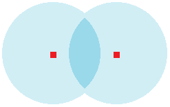
Therefore, and for the sake of learning, I would like to know if the following is possible (and if it is, how, in general lines, can it be achieved). Suppose we have, for the sake of simplicity, a point-mesh consisting of only two vertices (located in the 3D World space). Can we program a shader in a way such that each of these two vertices would be painted on screen at their exact WorldToViewport position, but also that a circle around each of them of radius=R is also painted in the surrounding pixels even if they extend beyond the original mesh to which the shader is attached? Like in the figure below (where the red square inthe center of the circles represents the vertices painted on screen):

enter image description here

If that is possible, can a shader also be programmed in such a way that these circles that extend beyond the vertices influence the color (RGBA) of each other? Like in the figure below:

enter image description here

As I said, if these are possible things, I would love to hear a bit of how to achieve such a thing - either in conceptual or practical terms. Is it done in the fragment shader, or has to be calculated before at the vertex or geometry shaders? How to calculate and pass "additional fragments" that extend beyond those fragments occupied by the mesh body?

$\endgroup$
1
  • $\begingroup$ A geometry shader may add more primitives than found in the original mesh. Does this do it for you? $\endgroup$
    – Andreas
    Commented May 17, 2016 at 17:41

2 Answers 2

6
$\begingroup$

When you use linewidth or line antialiasing or pointwidth or pointsprites, OpenGL creates for you a small rectangle instead of the line or point, with texture coordinates. Nowadays you can even program this yourself using geometry shaders ot even the tesselator.

A totally different approach is to use defered shading, using one geometric pass just to store information in the RGBAZ buffer, then a second pass than you run on all the pixels of the screen to do some process. (to act on all pixels, simply draw one full-screen rectangle). Nowadays you can even do the first pass as one or several "render to texture", then MIPmap these textures, so that the final pass can easily access to less local values.

$\endgroup$
3
  • $\begingroup$ Thanks! I have been doing what you've said at the beginning, using geometry shaders to create geometry around the points and so enable to draw pixels around the point. It works, of course, but its a more cumbersome solution. I got particularly interested in the last bits of what you've said: if I understood you correctly, what you mention is one could render the whole scene and then use a screen shader aimed at the area of interest and then do a pass over the rendered frame in order to work on how many pixels one wants around the points in the center? $\endgroup$ Commented May 20, 2016 at 0:06
  • $\begingroup$ You could render the first pass in a texture. Then in the second pass on full screen, in each pixel you could inspect the texture content in a disk around the pixel and do what you want (e.g. color according to the closest filled pixel, or paint white only if distance is below some threshold). Of course for just drawing disks, this is far from being the most efficient way ;-) $\endgroup$ Commented May 20, 2016 at 7:12
  • $\begingroup$ Sure, I just gave the simples example I could think of. But yes, I think what you say is in line with what I've been thinking, i.e. rendering to a texture in one pass and then later we have the information for, in other passes, alter pixels in relation to what lays in surrounding pixels. Many thanks. $\endgroup$ Commented May 20, 2016 at 9:04
3
$\begingroup$

One good way you can arrange for a circle (or other shape) to be drawn for each vertex in a mesh is to use geometry instancing. This is a GPU feature that allows multiple instances (copies) of a mesh to be drawn at once, with the vertices/indices of the mesh given by one set of buffers, and another vertex buffer that can give additional data per-instance. The vertex shader can be used to combine the data from both buffers in whatever way you choose.

To be concrete, in your case you could create a mesh representing a circle of the desired radius, with its vertices specified directly in screen-space coordinates and centered at the origin. Then you'd use instancing to make the GPU render a new copy of the circle mesh for every vertex of your original point-mesh. In the vertex shader, you'd calculate the screen-space position of the point (using the world-view-projection transforms as usual), then translate the circle mesh to be centered at that position.

As for the second part of your question, on how to have the circles influence each other's color: it depends on what you want to do, specifically. Hardware blending can be used to handle simple cases, such as adding or multiplying the colors, or alpha-blending. If you want something more complicated than that, then it might be possible to do it with a multi-pass algorithm, or (on the latest GPUs) programmable blending.

$\endgroup$

Your Answer

By clicking “Post Your Answer”, you agree to our terms of service and acknowledge you have read our privacy policy.

Not the answer you're looking for? Browse other questions tagged or ask your own question.