2
$\begingroup$

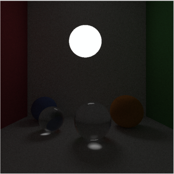
I implemented a spectral path tracing using physically base BRDF models such as Oren-Nayar,Specular Reflection and Transmission, Lambertian. All calculation in the path tracer uses standard illuminant and macbeth color checker SPD, spectral power distribution. The result of the path tracer for each pixel is the SPD obtained as a sum of SPD obtained from each sample calculated by the pat tracer. This SPD is then converted to CIE XYZ color and to RGB. The result scene obtained is the following one (in this example taking 500 samples per pixel):

enter image description here

As you can see, everything seems fine, except for the brightness/luminance of the scene. Every object in the scene is darker than it have to be. The floor and the front wall of the cornell box in the scene must be white and neutral8 (from macbeth color checker), but they are dark gray. The following method is the one that trace the samples for a pixel of the path tracer:

Vector3D PathTracer::getPixelColor(const Ray& ray, int bounce) {

    Spectrum<constant::spectrumSamples> L(0.0f);
    int numberOfSamples = 500;
    float sampleWeight = 1.0f/(float)numberOfSamples;

    for (int i = 0; i < numberOfSamples; i++) {

        Spectrum<constant::spectrumSamples> spectrumSample = trace(ray, bounce);
        L = L + spectrumSample * sampleWeight;
    }

    Spectrum<constant::spectrumSamples> Li = scene->light->spectrum;

    ColorMatchingFunction* colorMatchingFunction = new Standard2ObserverColorMatchingFunction();

    //Get tristimulus values.
    Vector3D tristimulus = CIE1931XYZ::tristimulusValues(L, Li, colorMatchingFunction);

    //Convert tristimulus to sRGB.
    Vector3D color = CIE1931XYZ::tristimulusTosRGB(tristimulus);

    //Apply sRGB gamma correction.
    sRGB::sRGBGammaCorrection(color, GammaCompanding);

    //Convert to standard 0 - 255 RGB value.
    sRGB::sRGBStandardRange(color);

    delete colorMatchingFunction;

    return color;
}

As you can seen, I already apply a gamma correction to the color obtained. Do you have any idea why my image rendered is so dark? My concerns are in the part where I convert the SPD sum, obtained from the samples, into RGB color. Do you see any error? Am I missing something? Do I need other operation to execute a correct conversion from the SPD obtained from the sampling to an RGB color?


To avoid to write a too long question, I will link the main classes used by the path tracer for the calculation:

The other files/classes used are all on this repository (branch luminance)

https://github.com/chicio/Spectrum-Clara-Lux-Tracer/tree/luminance


Thanks you all guys, I hope someone could help me.
$\endgroup$
15
  • $\begingroup$ It is perfectly OK if your material looks dark gray if you illuminate it with weak light source. What is the brightness of the light source? $\endgroup$
    – ivokabel
    Commented Mar 20, 2016 at 23:14
  • $\begingroup$ @ivokabel but my materials should look white and light gray. The SPD of the illuminant used is the D65. Do i need to tweak the spd of the light in some way? $\endgroup$ Commented Mar 20, 2016 at 23:17
  • $\begingroup$ @ivokabel Do i need to define a brightness paramter and use it somewhere? $\endgroup$ Commented Mar 20, 2016 at 23:17
  • $\begingroup$ If I am not mistaken, D65 only defines the shape of the spectrum, not the intensity. Therefore, you will really have to add a parameter telling the amount of emitting radiance, or something similar. Related topic is the renderer exposure value, but I saw that you take 1 as the limit value, so you don't have to bother with this one. $\endgroup$
    – ivokabel
    Commented Mar 20, 2016 at 23:37
  • $\begingroup$ Thank you @ivokabel for the suggestion about the parameter radiance. Could it be just a constant that will be multiplied with the spd of the illuminant during the tracing of rays? Or do i need to multiply the spd of the illuminant during the conversion from spd to cie xyz? Also I don't understand what you mean with renderer exposure value. Where do I take 1 as its value? $\endgroup$ Commented Mar 20, 2016 at 23:45

1 Answer 1

7
$\begingroup$

The problem lies mainly in CIE1931XYZ::tristimulusValues() function, where you normalize the resulting color to the luminance of your illuminant which causes that directly observed light source has luminance 1, but everything else is much darker. That is a nice thing to do if you just want to visualize colours of various reflectance spectra under a given illumination, but is probably not the best thing to do in a global illumination renderer.

To be more specific, you cannot expect a reflectance profile to be rendered always completely white just because it reflects all incident energy (constant spectral reflectance equal to 1 everywhere). Neglecting the material directional properties (BSDF, etc.), the properties of the light reflected from a point depend both on reflectance spectral profile of the material, and on the spectral and angular properties of the incident light. The incident light therefore depends not only on the SPD of the illuminant used for your light source, but also on its size and distance from the shaded point. The points closer to the light source will be brighter, while distant points will be darker.

I would suggest removing the luminance normalization in your Spectrum-to-XYZ conversion completely and then adjusting the overall brightness of your scene by multiplying the normalized SPD of the used illuminant (D65 in your case) with some brightness parameter. Whether you multiply it before rendering, during rendering or during the XYZ conversion step is completely up to you. The choice shouldn't affect the result.

$\endgroup$
7
  • $\begingroup$ Did this solve the problem? $\endgroup$
    – ivokabel
    Commented Mar 25, 2016 at 17:06
  • $\begingroup$ Hi @ivokabel, sorry for the late reply. You advice was good, and point me in the right direction, but was not enough. Indeed adding a brightness parameter to the light to manage the spectrum of the light. But i also added another parameter to manage the total luminance of a pixel: the tristimulus value obtained from the path tracer is multiply with the total radiance of the pixel (sum of each SPD wavelenght of the pixel). In this way the image brightness is good. $\endgroup$ Commented Apr 26, 2016 at 11:49
  • $\begingroup$ This is an example: drive.google.com/open?id=0BxeVnHLvT8-7MFNuN1pDcG1DZjg. Anyway thank you again. I hope to find a completely physically based solution before the end of my thesis time. $\endgroup$ Commented Apr 26, 2016 at 11:49
  • $\begingroup$ @FabrizioDuroni, does it mean, that adjusting the power of your light source with the brightness parameter doesn't make the resulting picture bright enough? I think I am missing something and I'm afraid you are adding to much alchemy into it ;-) Anyway, I'm glad it helped at least partially. $\endgroup$
    – ivokabel
    Commented May 23, 2016 at 20:04
  • $\begingroup$ I was missing something too, and in fact i remove that strange "alchemy" that i though was the right thing to do (web is not always a good source :D) Just a brightness multipler is good. This parameter could be substituted with more physically correct values, like the light power (using a Rienmann sum to calculate the integrate the light SPD ) and its area. But for my thesis has been decided that the brightness parameter is enough. $\endgroup$ Commented May 24, 2016 at 20:06

Your Answer

By clicking “Post Your Answer”, you agree to our terms of service and acknowledge you have read our privacy policy.

Not the answer you're looking for? Browse other questions tagged or ask your own question.