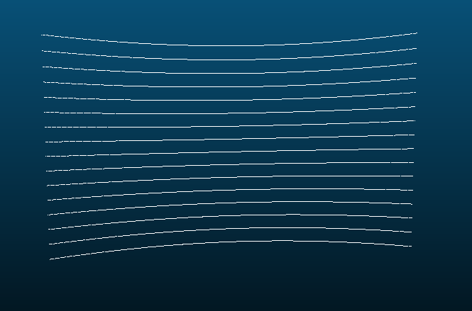
I'm attempting to perform an intersection test using ray casting (not sure if correct term so please forgive me if not) and am outputting the intersections as a point cloud, and the point cloud shows curvature (on the Z-axis only, the point cloud is completely flat on the Y axis, and the horizontal axis in this image is the X axis):

I borrowed concepts from the Scratchapixel site, specifically http://scratchapixel.com/lessons/3d-basic-rendering/minimal-ray-tracer-rendering-simple-shapes/ray-box-intersection.
Essentially, I am generating 16 rays, all with the same origin vector. The direction vectors start at +15 degrees on the YZ plane, and continue in increments of -2 degrees down to -15. I have an axis aligned bounding box that I am testing intersection with. I use a rotation transform to rotate the 16 rays CCW around the Z axis. I am performing the intersection test for all 16 rays each 0.1 degrees, and if it returns true, I add the point to the point cloud.
Here's my intersection code:
bool test_intersect(Box b, Ray r, Vec3f& intersect_point)
{
    float txmin = 0.0f, txmax = 0.0f, tymin = 0.0f, tymax = 0.0f, tzmin = 0.0f, tzmax = 0.0f;
    float t_min = 0.0f, t_max = 0.0f, t = 0.0f;

    // Determine inverse direction of ray to alleviate 0 = -0 issues
    Vec3f inverse_direction(1 / r.direction.x, 1 / r.direction.y, 1 / r.direction.z);

    // Solving box_min/box_max0 = O + Dt
    txmin = (b.box_min.x - r.origin.x) * inverse_direction.x;
    txmax = (b.box_max.x - r.origin.x) * inverse_direction.x;
    tymin = (b.box_min.y - r.origin.y) * inverse_direction.y;
    tymax = (b.box_max.y - r.origin.y) * inverse_direction.y;
    tzmin = (b.box_min.z - r.origin.z) * inverse_direction.z;
    tzmax = (b.box_max.z - r.origin.z) * inverse_direction.z;

    // Depending on direction of ray tmin may > tmax, so we may need to swap
    if (txmin > txmax) std::swap(txmin, txmax);
    if (tymin > tymax) std::swap(tymin, tymax);
    if (tzmin > tzmax) std::swap(tzmin, tzmax);

    t_min = txmin;
    t_max = txmax;

    // If t-value of a min is greater than t-value of max,
    // we missed the object in that plane.
    if ((t_min > tymax) || (tymin > t_max))
        return false;

    if (tymin > t_min)
        t_min = tymin;
    if (tymax < t_max)
        t_max = tymax;

    if ((t_min > tzmax) || (tzmin > t_max))
        return false;

    if (tzmin > t_min)
        t_min = tzmin;
    if (tzmax < t_max)
        t_max = tzmax;

    if (t_min > 0)
        t = t_min;
    else
        if (t_max > 0)
            t = t_max;
        else
            return false;

    intersect_point.x = r.origin.x + r.direction.x * t;
    intersect_point.y = r.origin.y + r.direction.y * t;
    intersect_point.z = r.origin.z + r.direction.z * t;

    return true;

}
And my rotation:
// Rotation around z axis, for rotating array and checking beam intersections
void transform_rotate_z(Vec3f& in_vector, float angle)
{
    float radians = angle * (M_PI / 180);

    float result_x = cos(radians) * in_vector.x + -sin(radians) * in_vector.y;
    float result_y = sin(radians) * in_vector.x + cos(radians) * in_vector.y;
    in_vector.x = result_x;
    in_vector.y = result_y;

}
I have racked my brain for quite a while but I can't seem to determine how I can prevent this curvature, I'm sure I'm overlooking something simple. I'd be grateful for any help you can provide.
EDIT 9/18/16: It turned out that I had incorrectly believed that physical LIDAR units had some algorithmic way of "straightening" out the curves, which is not the case! The output is supposed to look like the picture above.