I'm trying to implement a basic form of physically based rendering (PBR) and I am using the PBR tutorial from learnopengl dot com as a reference.
The PBR I am implementing consists of two parts, direct illumination and indirect illumination. The direct illumination is quite straight forward and is working as expected (well, according to my untrained eye...). It's the indirect illumination that I'm having troubles implementing. I want to use image based lighting (IBL) for this part.
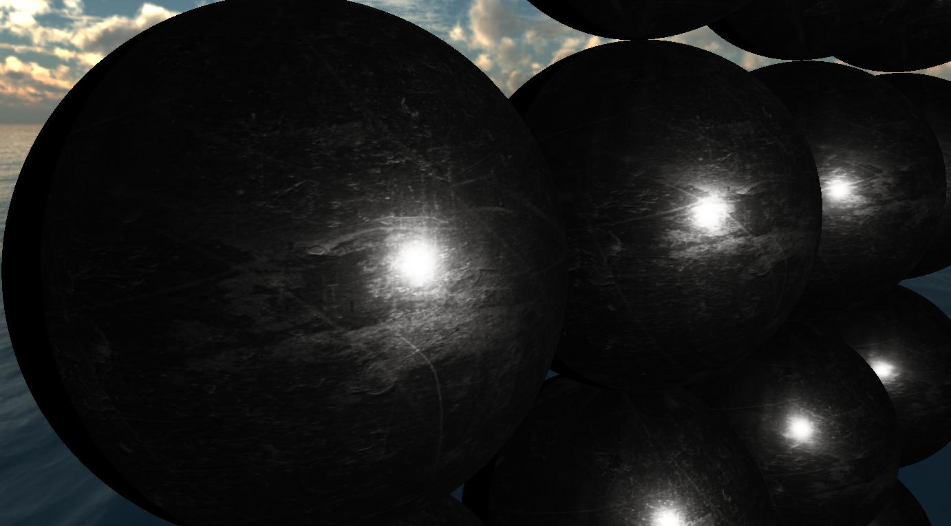
The following image showcases the output after rendering spheres with this scuffed titanium PBR metal material using only direct illumination.
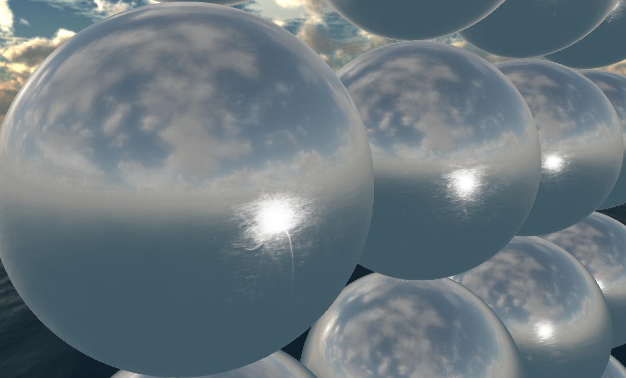
When I also include indirect illumination (from the environment map), this is what I get
I would've expected to see something much more like the preview picture from the page where I found the PBR material from, see link above.
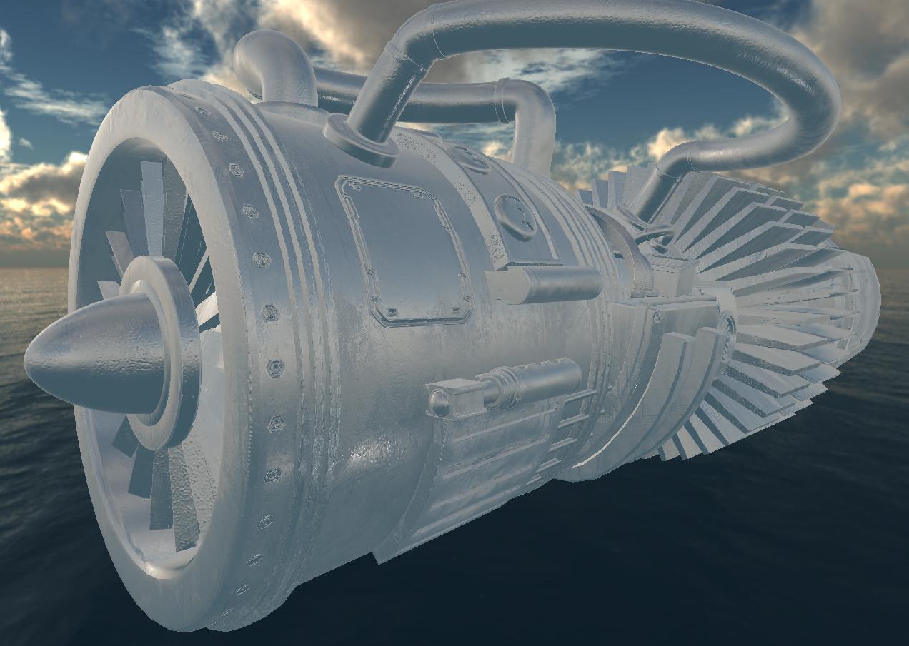
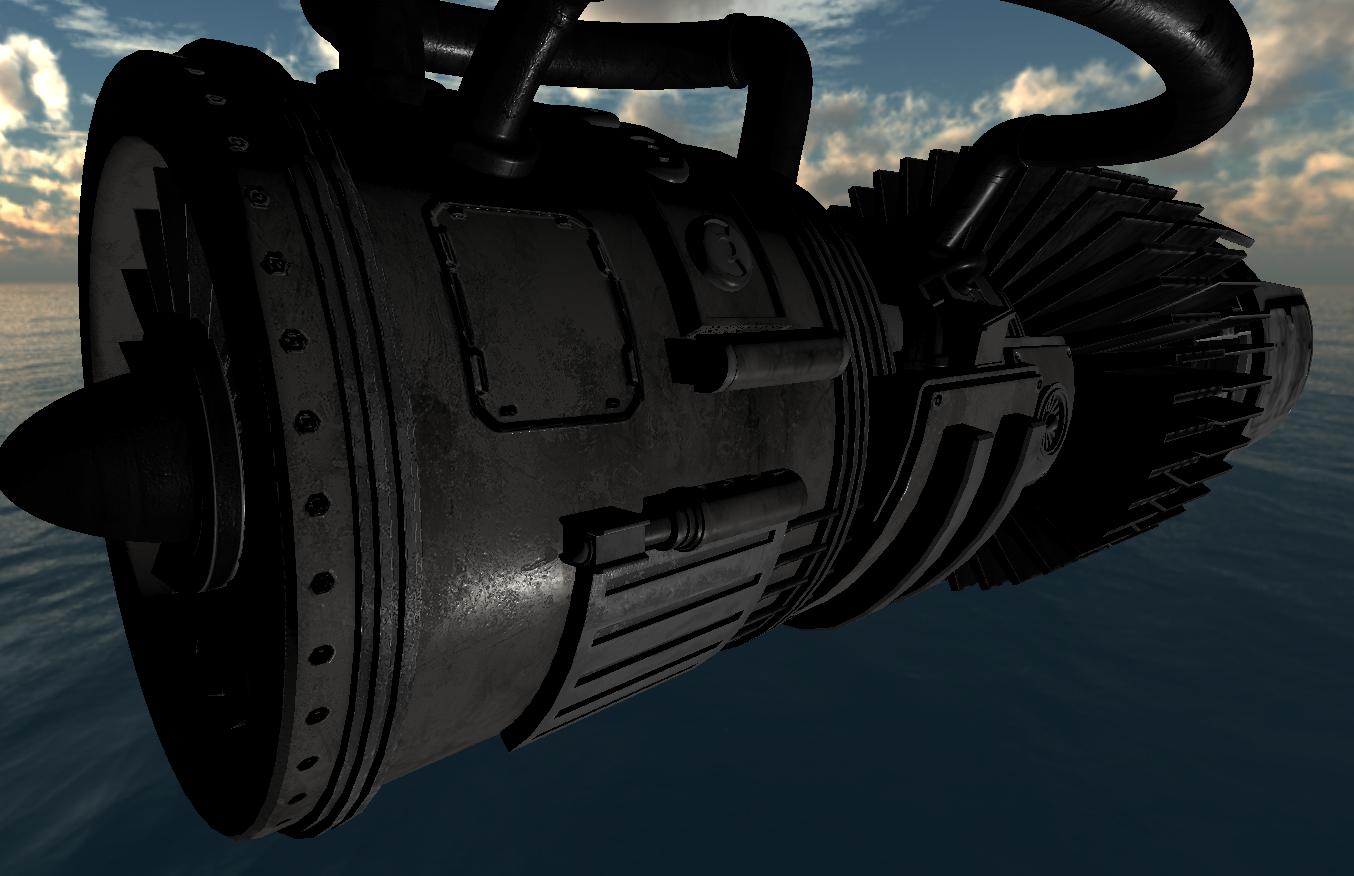
Here is another image of another more sophisticated model with direct and indirect illumination
if I remove the indirect illumination I get this
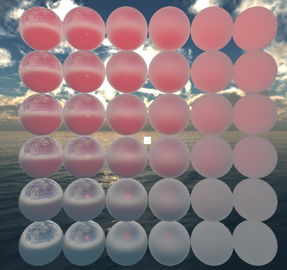
Instead the environment map seems to be overpowering everything which looks odd to me.
I am using a pre-convolved reflectance map that is mipmapped (7 HDR images in total) as well as an irradiance map (HDR image). These are correct and are not the issue.
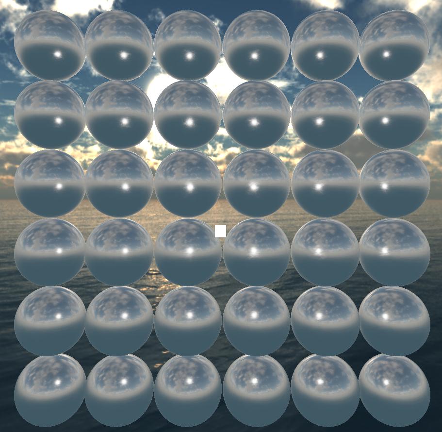
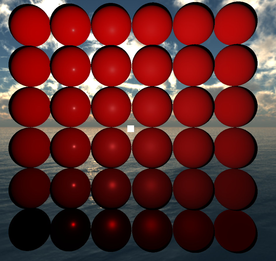
If I use a plain-sphere with a red base color and vary the metalness (growing vertically) and the roughness (growing horizontally) I get this with NO indirect illumination.
note how the left-most spheres (with roughness=0.0) have no specular reflection, that seems odd to me.
... with indirect illumination
I am not sure where I'm going wrong. Below you'll find the fragment shader used to render the seen images (excluding the last shown image)
#version 460 core

#define EPSILON 0.00001
#define PI 3.14159265359

/////////////////////////
// VERTEX SHADER INPUT //
/////////////////////////
in vec3 position; // world space
in vec3 normal;
in vec2 texcoord;

/////////////////////////
// Material properties //
/////////////////////////
struct Material {
    ...
};
layout (binding = 5) uniform sampler2D u_DiffuseMap;
layout (binding = 6) uniform sampler2D u_RoughnessMap;
layout (binding = 7) uniform sampler2D u_MetalnessMap;
layout (binding = 8) uniform sampler2D u_EmissionMap;
layout (binding = 9) uniform sampler2D u_NormalMap;
layout (binding = 11) uniform sampler2D u_AoMap;
uniform Material u_Material;

/////////////////////
// Environment map //
/////////////////////
layout (binding = 3) uniform sampler2D u_ReflectanceMap; // 8 maps in total, mipmapped
layout (binding = 4) uniform sampler2D u_IrradianceMap;

///////////////////////////
// Pointlight properties //
///////////////////////////
struct PointLight {
    vec3 position; // in world space
    vec3 color; // [0, 1]
};
uniform PointLight u_PointLights[1]; // only supporting one light source right now

////////////
// Camera //
////////////
uniform vec3 u_CameraPosition; // in world space

////////////
// OUTPUT //
////////////
out vec4 FragColor;

///////////////////////////////////////////////////////////////////////
///////////////////////////////////////////////////////////////////////
///////////////////////////////////////////////////////////////////////

vec3 getNormalFromMap()
{
    vec3 tangentNormal = texture(u_NormalMap, texcoord).xyz * 2.0 - 1.0;

    vec3 Q1  = dFdx(position);
    vec3 Q2  = dFdy(position);
    vec2 st1 = dFdx(texcoord);
    vec2 st2 = dFdy(texcoord);

    vec3 N  = normalize(normal);
    vec3 T  = normalize(Q1 * st2.t - Q2 * st1.t);
    vec3 B  = -normalize(cross(N, T));
    mat3 TBN = mat3(T, B, N);

    return normalize(TBN * tangentNormal);
}

float DistributionGGX(vec3 N, vec3 H, float roughness)
{
    float a = roughness*roughness;
    float a2 = a*a;
    float NdotH = max(dot(N, H), 0.0);
    float NdotH2 = NdotH*NdotH;

    float nom   = a2;
    float denom = (NdotH2 * (a2 - 1.0) + 1.0);
    denom = PI * denom * denom;

    return nom / denom;
}

float GeometrySchlickGGX(float NdotV, float roughness)
{
    float r = (roughness + 1.0);
    float k = (r*r) / 8.0;

    float nom   = NdotV;
    float denom = NdotV * (1.0 - k) + k;

    return nom / denom;
}

float GeometrySmith(vec3 N, vec3 V, vec3 L, float roughness)
{
    float NdotV = max(dot(N, V), 0.0);
    float NdotL = max(dot(N, L), 0.0);
    float ggx2 = GeometrySchlickGGX(NdotV, roughness);
    float ggx1 = GeometrySchlickGGX(NdotL, roughness);

    return ggx1 * ggx2;
}

vec3 fresnelSchlick(float cosTheta, vec3 F0)
{
    return F0 + (1.0 - F0) * pow(clamp(1.0 - cosTheta, 0.0, 1.0), 5.0);
}

vec3 fresnelSchlickRoughness(float cosTheta, vec3 F0, float roughness)
{
    return F0 + (max(vec3(1.0 - roughness), F0) - F0) * pow(clamp(1.0 - cosTheta, 0.0, 1.0), 5.0);
}

///////////////////////////////////////////////////////////////////////
///////////////////////////////////////////////////////////////////////
///////////////////////////////////////////////////////////////////////

void main()
{

    // NOTE: Lighting calculations being done in world space.

    vec3 baseColor = u_Material.color;
    if (u_Material.has_color_texture)
        baseColor = texture(u_DiffuseMap, texcoord).rgb;

    float metalness = u_Material.metalness;
    if (u_Material.has_metalness_texture)
        metalness = texture(u_MetalnessMap, texcoord).r;

    float roughness = u_Material.roughness;
    if (u_Material.has_roughness_texture)
        roughness = texture(u_RoughnessMap, texcoord).r;

    vec3 emission = u_Material.emission;
    if (u_Material.has_emission_texture)
        emission = texture(u_EmissionMap, texcoord).rgb;

    vec3 N = normalize(normal);
    if (u_Material.has_normal_texture)
        N = getNormalFromMap();

    float ao = 0.0;
    if (u_Material.has_ao_texture)
        ao = texture(u_AoMap, texcoord).r;

    vec3 V = normalize(u_CameraPosition - position);

    // Disney us
    vec3 F0 = vec3(0.04);
    F0 = mix(F0, baseColor, metalness);

    vec3 Lo = vec3(0.0);
    for(int i = 0; i < 1; i++) // only 1 pointlight at the moment
    {
        vec3 L = u_PointLights[i].position - position;
        vec3 H = normalize(V + normalize(L));
        float d = length(L);
        float attenuation = 1.0 / (d * d);
        vec3 radiance = 125 * u_PointLights[i].color * attenuation;
        // --------------^ pointlight_intensity, without envmap
        //                 objects come out way too dark without this factor.
        //                 What's a good number depends on scene.

        float NDF = DistributionGGX(N, H, roughness);
        float G = GeometrySmith(N, V, L, roughness);
        vec3 F = fresnelSchlick(max(dot(H, V), 0.0), F0);

        // Cook-Torrance model
        vec3 numerator = NDF * G * F;
        float denominator = 4.0 * max(dot(N, V), 0.0) * max(dot(N, L), 0.0) + EPSILON;
        vec3 specular = numerator / denominator;

        vec3 kS = F;
        vec3 kD = vec3(1.0) - kS;
        kD *= 1.0 - metalness;

        float NdotL = max(dot(N, L), 0.0);

        Lo += (kD * baseColor / PI + specular) * radiance * NdotL;
    }

    vec3 F = fresnelSchlickRoughness(max(dot(N, V), 0.0), F0, roughness);

    vec3 kS = F;
    vec3 kD = 1.0 - kS;
    kD *= 1.0 - metalness;

    // Sample irradiance map
    float theta = acos(max(-1.0f, min(1.0f, N.y)));
    float phi = atan(N.z, N.x);
    if(phi < 0.0f)
        phi = phi + 2.0f * PI;
    vec2 lookup = vec2(phi / (2.0 * PI), 1 - theta / PI);
    vec3 irradiance = texture(u_IrradianceMap, lookup).rgb;
    vec3 diffuse = irradiance * baseColor;

    // Sample reflectance map
    vec3 wi = normalize(reflect(-V, N));
    float theta2 = acos(max(-1.0f, min(1.0f, wi.y)));
    float phi2 = atan(wi.z, wi.x);
    if(phi2 < 0.0f)
        phi2 = phi2 + 2.0f * PI;
    vec2 lookup2 = vec2(phi2 / (2.0 * PI), 1 - theta2 / PI);
    const float MAX_LOD = 7.0;
    vec3 specular = textureLod(u_ReflectanceMap, lookup2, roughness * MAX_LOD).rgb;

    vec3 ambient = (kD * diffuse + specular) * ao;

    /////////////////////////////////////

    vec3 color = ambient + emission + Lo;

    // HDR tonemapping
    color = color / (color + vec3(1.0));
    // gamma correct
    color = pow(color, vec3(1.0/2.2));

    FragColor = vec4(color, 1.0);
}
