3
$\begingroup$

I am writing a raytracer which is meant to support shadows. Previously, I have naively implemented hard shadows by casting a shadow ray towards the light (+ offset) and seeing if it hits anything along the way. This worked great, but now I am challenging myself by adding support for dielectrics and transparency in general.

Intuitively, I wanted to make my shadow rays refract if they hit an object on the way to the light. However, it turns out this is pretty difficult to do. I then found this post which explains that I can just ignore refraction for a good enough approximation. Therefore:

  • How does the final result change depending on if you refract the shadow ray or not? I am having a hard time trying to visualize it, are there maybe any side by side comparisons?
  • The answer also mentions photon mapping. Alternatively, is it not possible to solve for the angle you need to shoot in order to end up at the light after refracting many times? Should this not end up being a linear system of equations? Or do we not do this because it is computationally too intense?
  • Are there any heuristics or rules of thumbs for when you should start actually modelling it in a physically realistic way (i.e. refract shadow rays)? Does the number of dielectrics in the scene affect this?

Now, assuming that I do cast a straight shadow ray and beteen a point and the light there is a semi-transparent (50% opaque) purple surface.

  • So, half the light should go through. Does that mean I multiply the surface's colour by half the intensity of the light and then shade the area under the surface like I would shade any surface normally? Or do I just set the surface colour to be half the intensity of the light multiplied by purple?
  • What happens if I have many surfaces stacked on top of eachother? Say I have 3 purple surfaces all stacked perfectly on top of each other, with a vertical distance between them. The light shines straight down. I'm guessing that the intensity of the light with initial intensity $i$ would be as follows: after the first surface, it is $\frac{i}{2}$, then $\frac{i}{4}$ and lastly the point sees $\frac{i}{8}$ of the original intensity?
$\endgroup$

1 Answer 1

3
$\begingroup$

"Refracting the shadow ray" is really the wrong mental model to use to think about this. After all, shadow rays are not real things; light rays are. Shadow rays are only used to test for some geometry blocking a light ray that could otherwise be there.

What you're really asking about is: how do I go from simulating only direct lighting paths (light goes straight from source to the illuminated surface) to incorporating indirect specular paths as well (light gets to the illuminated surface through some set of specular refractions/reflections).

How does the final result change depending on if you refract the shadow ray or not? I am having a hard time trying to visualize it, are there maybe any side by side comparisons?

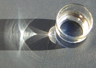
In general, light from a light source refracting through a transparent object and illuminating a surface will produce caustics, as in this image from Wikipedia:

light shining on a glass of water producing caustics on the table

You can see here the ordinary shadow due to interruption of the direct light path from source to the tabletop (this is the same shape as if the glass were opaque), plus a very complex pattern of extra light that's produced where the refraction through water and glass happens to focus more of the incident light rays. All the light that would have filled in the shadowed area if the water glass wasn't there has instead gotten pushed around, removed from some areas and concentrated in others, resulting in this pattern.

is it not possible to solve for the angle you need to shoot in order to end up at the light after refracting many times? Should this not end up being a linear system of equations?

Perhaps in the case of some exceedingly simple geometry, like a point light and a single perfect sphere, this could be done. In general, it is far too complex to handle this way. It certainly is not as simple as some linear equations. After all, look at the complexity of the caustics above, which is the result of essentially two nested cylinders. Really, the way to handle this is with photon mapping, or other advanced path tracing approaches like path guiding or VCM.

Are there any heuristics or rules of thumbs for when you should start actually modelling it in a physically realistic way?

It depends on the scene, and it depends how much realism you want vs how much computational budget you have, as caustics are expensive to simulate. A rule of thumb could be if you have any highly specular (low roughness) surfaces in or near the camera's field of view, and exposed to a small bright light source. Those are the cases where caustics will probably be most visible.

So, half the light should go through. Does that mean I multiply the surface's colour by half the intensity of the light and then shade the area under the surface like I would shade any surface normally? Or do I just set the surface colour to be half the intensity of the light multiplied by purple?

This gets into the interpretation of what your transparent surface is. When you say it is purple, does that mean it applies a purple tint to the light that passes through it? If so, then you should multiply the light color by purple. Or does the surface reflect/scatter purple light? In that case the light that passes through it would actually get a green tint (the complementary color to purple) since it will have its purple component filtered out of it. This is what happens with air on a clear day: it scatters blue light (producing the blue sky) and applies a yellow/orange tint to sunlight passing through it.

BTW, to be more physically accurate, a color tint is not imparted by a surface but by a medium, and it depends on how far the ray travels through the medium. If you want to model tinted but clear (not cloudy) transparent materials, you can look up some material about Beer's Law, which governs that.

I'm guessing that the intensity of the light with initial intensity $i$ would be as follows: after the first surface, it is $\frac{i}{2}$, then $\frac{i}{4}$ and lastly the point sees $\frac{i}{8}$ of the original intensity?

That's right, the attenuation of each layer stacks as you add more layers.

$\endgroup$
4
  • 1
    $\begingroup$ I am not sure what a transparent surface would be. I vividly remember as a child having a balloon that had a colourful shadow like this. I suppose this would be "applies a purple tint to the light"? And, if a surface scatters/reflects purple light, would that be defined in the material as a Kd/Ks of <1, 0, 1>? Then in contrast, what would the Kd/Ks look like of a material that applies a tint to the light? $\endgroup$ Commented Dec 20, 2021 at 21:24
  • 1
    $\begingroup$ Yeah, colored shadows like that mean that the light passing through is getting some of the wavelengths filtered out, aka it's tinted. The Kd/Ks coefficients don't describe tinting of transmitted light; you'd need another coefficient, Kt if you like, for that. $\endgroup$ Commented Dec 21, 2021 at 7:04
  • 1
    $\begingroup$ So if I am given a material in MTL format from e.g. Blender, I can assume that the colours will not be tinted, rather that all shadows will be grayscale, and the darkness depends on how much of the light is able to pass through the surface? $\endgroup$ Commented Dec 21, 2021 at 10:08
  • 1
    $\begingroup$ Yeah, the MTL format doesn't appear to have any setting for tinted transparency, only for grayscale alpha which it calls "dissolve". $\endgroup$ Commented Dec 21, 2021 at 16:01

Your Answer

By clicking “Post Your Answer”, you agree to our terms of service and acknowledge you have read our privacy policy.

Not the answer you're looking for? Browse other questions tagged or ask your own question.