6
$\begingroup$

I'm trying to find the angle it would take for me to rotate a polygon so that a specific side is completely horizontal and on the bottom.

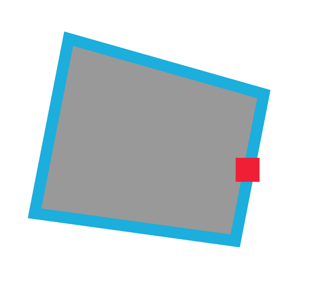
For example, a shape like this: enter image description here

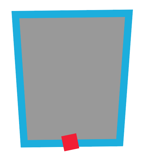
Needs to be rotated so the side with the red square on it is on the bottom and completely horizontal, like this:

enter image description here

So far I've tried several approaches but all end up having strange edge cases where the angle is incorrect.

$\endgroup$
1
  • $\begingroup$ Welcome to Computer Graphics Stack Exchange. You could improve your question by adding what information about the polygon and the red box you have. Do you e.g. know the precise coordinates of the vertices, or do you only have the image? Also, please describe what you already tried to do. These information will help us to write good answers and especially also one that helps you best. Some more tips can be found on our How to Ask page in our Help Center. $\endgroup$
    – Nero
    Commented Jan 1, 2016 at 22:09

2 Answers 2

3
$\begingroup$

Deducing the angle and rotating by that angle works quite well in 2D (describe in TLousky's post). This strategy, does not extend very well into three-dimensional realm. I will provide an alternative solution that shows a general strategy that works in a larger set of cases. As a bonus this without needing to think of trigonometry as it can be encoded away.

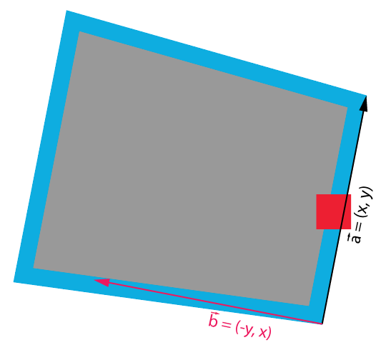
  1. First identify the vector that you want to be transformed to orientation in your reference space. Let us call this vector $\vec{a}$, or a along vector.

  2. Next you will need to identify a vector that is perpendicular to this vector. Let us call this vector $\vec{b}$, it is sometimes also called a up vector. In three-dimensions you need 3 vectors but once you identify 2 you can compute the third.

    Finding out the $\vec{b}$ in 2-D realm is especially easy you could just rotate the vector by $90^{\circ}$ or simply swap the coordinates and make the x coordinate negative (see 1). Alternatively you can use the same procedure as in 3D.

    $$\vec{b} = rotate(90^{\circ})\cdot\vec{a} = \begin{bmatrix} \cos(\pi/2) & -\sin(\pi/2) \\ \sin(\pi/2) & \cos(\pi/2) \end{bmatrix} \begin{bmatrix} x \\ y \end{bmatrix} = \begin{bmatrix} -y \\ x \end{bmatrix} \tag{1}$$

    In 3-D this usually requires a trick. Since each triangle is flat, one can use this to ones advantage. This gives us a perpendicular direction, now we still need a third one and we can get it by cross product of the 2 known vectors. You now have 3 vector.

    enter image description here

    Image 1: Vector $\vec{a}$ and derived $\vec{b}$

  3. Normalize the vectors

  4. Use these vectors to produce a a rotation matrix (or a affine matrix wich allows you to specify point to be at zero, your choice). This matrix represents the local coordinate of the rotated object.

  5. All you now need is to invert this matrix and point matrix multiply your polygon corner vectors for a aligned version of the polygon.

What is especially nifty is the sidestepping of trigonometrical operations. Now i see no point i defining basic matrix operations but i see value in code. So i will use numpy.

import numpy as np, pylab

pts = np.array([
        [0.,0.],[10.,1.],[12.,12.],[-2.,11.],[0.,0.]
      ]).transpose()

f = pylab.figure(facecolor="1.")     
pylab.axis('off')
pylab.axis('equal')
pylab.plot(pts[0], pts[1])  

# 1. Get the vector
vec_a = np.copy(pts[:,2]) - np.copy(pts[:,1])

# 2. up vector
vec_b = np.copy(vec_a[::-1])
vec_b[0] *= -1

# 3. normalize
vec_a /= np.linalg.norm(vec_a)
vec_b /= np.linalg.norm(vec_b)

# 4. build rotation matrix
mtx_R = np.concatenate(([vec_a], [vec_b])).transpose()
mtx_R = np.linalg.inv(mtx_R)

# 5. transform, or set hierarchy transform
pts2 = np.copy(pts)
for i in range(len(pts2[0])):
    pts2[:,i] =  np.dot(mtx_R, pts2[:,i])

pylab.plot(pts2[0],pts2[1])
pylab.show()

I admit it cold be have slightly shorter by refactoring the code and eliminate redundant manipulations but its a demo only so...

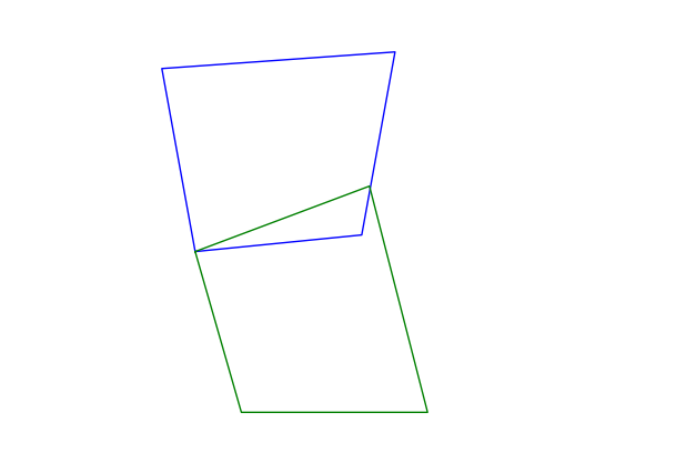
enter image description here

Image 2: Polygon, in blue axis fixed in green.

Same method works well for straightening, skew and other problems such as perspective correction. You can extend this to affine matrices that way you can encode the translation into the calculation with just 1 more lines. In essence you specify what point is at origin and with 2 more operations one could define around what to rotate. Now it just just rotates about the origin.

$\endgroup$
2
$\begingroup$

This algorithm is based on this answer for finding the angle between vectors, and this answer for rotating polygon points. It's written in Python, and assumes you want to align an edge with the X axis (horizontal axis). If you want to align it with the Y axis, replace the xVec in the code below with a yVec = [0,1].

EDITED: Added code for rotating the polygon and displaying the original and rotated polygons. Result of this script is displayed in the image below:
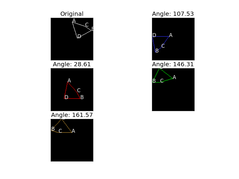
enter image description here

from PIL import Image, ImageDraw
from matplotlib import pyplot as plt
from math import radians, degrees, sqrt, acos, cos, sin

def dotproduct(v1, v2):
  return sum( (a*b) for a, b in zip(v1, v2) )

def length(v):
  return sqrt( dotproduct(v, v) )

def angle(v1, v2):
  return acos( dotproduct(v1, v2) / ( length(v1) * length(v2) ) )

def vec_subtraction( v1, v2 ):
    return [ e1 - e2 for e1, e2 in zip( v1, v2 ) ]

def calc_edge_vec( poly, edge ):
    p1 = poly['points'][ edge[0] ]
    p2 = poly['points'][ edge[1] ]

    return vec_subtraction( p2, p1 )

def rotatePolygon( poly, theta ):
    ''' Rotates the given polygon which consists of corners represented
        as (x,y), around the ORIGIN, clock-wise, theta degrees
    '''

    rotatedPolygon = []
    for corner in poly:
        rotatedPolygon.append((
            corner[0] * cos( theta ) - corner[1] * sin( theta ), # x
            corner[0] * sin( theta ) + corner[1] * cos( theta )  # y
        ))

    # Make sure rotated polygon coordinates are within image boundaries
    minX = min( [ c[0] for c in rotatedPolygon ] ) * -1
    minX = minX if minX > 0 else 0
    minY = min( [ c[1] for c in rotatedPolygon ] ) * -1
    minY = minY if minY > 0 else 0

    rotatedPolygon = [ ( x + minX, y + minY ) for x, y in rotatedPolygon ]

    return rotatedPolygon

def draw_and_plot_polygon( im, poly, color, plotTitle, plotIndex ):
    draw = ImageDraw.Draw( im )

    for e in poly['edges']:
        p1 = tuple( poly['points'][ e[0] ] )
        p2 = tuple( poly['points'][ e[1] ] )
        draw.line( [p1, p2], fill = color )

    del draw

    plt.subplot( 3, 2, plotIndex ),
    plt.imshow( im ),
    plt.title( plotTitle ),
    plt.xticks([]), plt.yticks([])

    # Draw point names (ABCD)
    for i, c in enumerate( poly['points'] ):
        plt.text( c[0], c[1], "ABCD"[i], color = 'white' )

# Define polygon as dictionary of point coordinates and edges
# each edge is a pair of point indices
p = {
    'points' : [ (50,10), (95,30), (80,20), (62,48) ],
    'edges'  : [ (3,0), (3,1), (1,2), (2,0) ]
}

xVec = [1,0] # Horizontal axis

# Draw original poly in white
im = Image.new( 'RGB', (100,100) )
draw_and_plot_polygon( im, p, (255,255,255), 'Original', 1 )

colors = [ (50,50,255), (255,0,0), (0,255,0), (200, 150, 50) ]

i = 2
for e, color in zip( p['edges'], colors ):
    edgeVec = calc_edge_vec( p, e )
    a       = angle( edgeVec, xVec )

    rotPol = p.copy()
    rotPol['points'] = rotatePolygon( p['points'], a )

    im = Image.new( 'RGB', (100,100) )

    # Place aligned edge at bottom
    alingedEdgeY = im.size[1] - rotPol['points'][ e[0] ][ 1 ] # Current edge height
    rotPol['points'] = [ ( p[0], p[1] + alingedEdgeY ) for p in rotPol['points'] ]

    # Draw rotated polygon
    angleTitle = "Angle: " + str( round( degrees(a), 2 ) )
    draw_and_plot_polygon( im, rotPol, color, angleTitle, i )

    i += 1

plt.show()

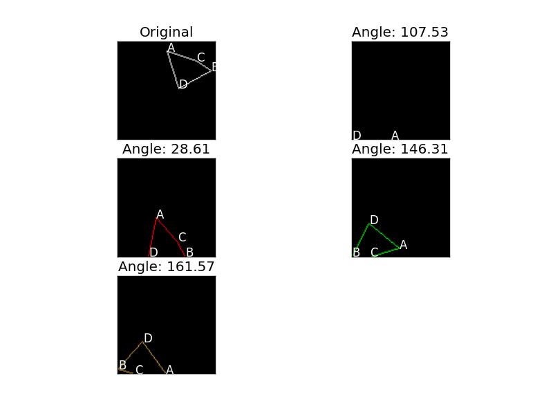
EDITED 2: Added some code to position the rotated polygon so that the aligned edge is on the floor (lines 90-91). Here's the result: enter image description here
$\endgroup$
4
  • $\begingroup$ Note that the question also requires the specified edge to be at the bottom. $\endgroup$ Commented Jan 2, 2016 at 23:40
  • $\begingroup$ @trichoplax, right. Added that bit of code. $\endgroup$
    – TLousky
    Commented Jan 3, 2016 at 5:34
  • $\begingroup$ From the example in the question, I believe "at the bottom" means that the horizontal edge becomes the base of the shape, rather than moving it to the bottom of the screen. $\endgroup$ Commented Jan 3, 2016 at 14:14
  • $\begingroup$ For instance, your side AD is at the top of the shape, so that even when it is moved to the bottom of the screen, the rest of the shape is still below it, off screen. $\endgroup$ Commented Jan 3, 2016 at 14:15

Your Answer

By clicking “Post Your Answer”, you agree to our terms of service and acknowledge you have read our privacy policy.

Not the answer you're looking for? Browse other questions tagged or ask your own question.