1
$\begingroup$

I'm doing my own engine in college to display a wireframe on screen with an isometric projection but I literally can't find any literature about maths behind doing it by hand just for game engines which I'm not allowed to use.

So how can I get implement an isometric projection by hand?

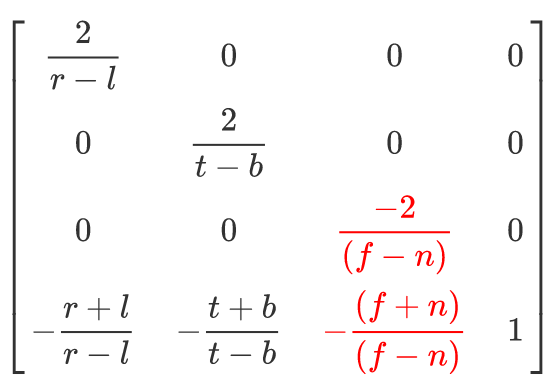
my projection matrix (row-major): Row-major

$\endgroup$
3
  • $\begingroup$ What about the "Mathematics" section in the Wikipedia article? $\endgroup$
    – wychmaster
    Commented Jun 28, 2022 at 13:45
  • $\begingroup$ I tried that and it didn't work at all with my projection matrix $\endgroup$
    – MiguelP
    Commented Jun 28, 2022 at 14:11
  • $\begingroup$ I can't make sense of your parameters, please explain. A simple technique to obtain a parallel projection is by drawing the projection center to infinity and simultaneously magnifying by the remoteness. When you do that, some coefficients become constant in the limit. $\endgroup$
    – user1703
    Commented Apr 26, 2023 at 13:31

3 Answers 3

0
$\begingroup$

Another way to formulate an Isometric projection is with the matrix:

$ \left[ {\begin{array}{cc} cos(\phi) & sin(\phi)sin(\theta) & 0 & 0 \\ 0 & cos(\theta) & 0 &0 \\ sin(\phi) & -cos(\phi)sin(\theta) & 0 & 0 \\ 0 & 0 & 0 & 1 \\ \end{array} } \right] $

Where $\phi$ and $\theta$ are the two rotational angles.

Note that the 3rd column is all zero's indicating the plane of projection.

$\endgroup$
0
$\begingroup$

The projection matrix tells us how to draw an image. But how does it tell us this? Well it tells us what the original vectors are like when drawn on screen. The axonometric projections have fixed direction vectors, isometric is just one of them.

Now there is a entirely visually verifiable correlation between the matrix and the axes of your axonometric projection. You can offcourse also do this with rotations as others have suggested but its a very nonstraightforward way to achieve something you should be able to do by drawing the axes on a 2d surface.

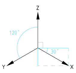
Now lets take the standard 120 forward facing isometric axes with z up (offcourse any coordinate could be flitted and you could have Y up as well just change sign or swap rows in matrix. Covnention random happens to be this since I was doing architectural stuff last and architects like z up since they draw in the X-Y plane. Had i worked with machanical engineers it would be Y up):
enter image description here

Each basis vector is just a row in the matrix. From this follows that in your camera matrix is of form:

$ \left[ {\begin{array}{cc} cos(30°) & -sin(30°) & z_x & 0 \\ -cos(30°) & -sin(30°) & z_y & 0 \\ 0 & 1 & z_z & 0 \\ c_x & c_y & c_z & 1 \\ \end{array} } \right] = \left[ {\begin{array}{cc} \sqrt{3}/2 & -1/2 & z_x & 0 \\ -\sqrt{3}/2 & -1/2 & z_y & 0 \\ 0 & 1 & z_z & 0 \\ c_x & c_y & c_z & 1 \\ \end{array} } \right] $

So the last column is 0 because it does not participate in a perspective. The variables $c$ represent the offset for your center. Then you may also want to multiply all the x y z components with a multiplier to fit your screen drawing coordinates, but that depends on your imaging system.

What about $z$? Well you want z values to be affected by your ground plane distance somehow. Now you could decompose all this to rotations to get a natural z value. Or you can just put in a value in $z_x$ and $z_y$ and see what happens its probably not all that important as long as your geometry does not clip by near and far planes.

Similarly since the vectors are just what you see you can make any axonometric projection by drawing your axes and feeding their 2d coordinates into your matrix.

NOTE: The matrix may be transposed depending on how your system calculation order works.
$\endgroup$
-2
$\begingroup$

I found that the easiest way is to just use a Transformation Matrix like: This bad boi

And just adjust the Rz(a) to 45º and Rx(g) to 35.264º

Or if -z to Rz(a) to -45º and Rx(g) to 215.264º

$\endgroup$
6
  • $\begingroup$ This is not an axonometric projection. $\endgroup$
    – pmw1234
    Commented Jun 29, 2022 at 11:10
  • $\begingroup$ It looks like you are adding a transformation matrix with the desired roll in the standard MVP (model view projection), an Isometric projection replaces the perspective projection shown in the original question. $\endgroup$
    – pmw1234
    Commented Jun 29, 2022 at 11:29
  • $\begingroup$ @pmw1234 can you elaborate further? As I understand your answer is the projection matrix? $\endgroup$
    – MiguelP
    Commented Jun 29, 2022 at 21:41
  • $\begingroup$ Your original question posted a perspective projection matrix. An isometric projection would replace that matrix, and it would be in the form posted in my answer. The matrix you posted is a transformation matrix that composes 3 rotations. A projection reduces the number of dimensions so I would expect 1 column of the matrix to be all zero's. $\endgroup$
    – pmw1234
    Commented Jul 1, 2022 at 17:29
  • $\begingroup$ projection matrices do not reduce the number of dimensions. The depth is preserved (in non-linear form) for use in z-buffering. $\endgroup$ Commented Jul 6, 2022 at 8:49

Your Answer

By clicking “Post Your Answer”, you agree to our terms of service and acknowledge you have read our privacy policy.

Not the answer you're looking for? Browse other questions tagged or ask your own question.