2
$\begingroup$

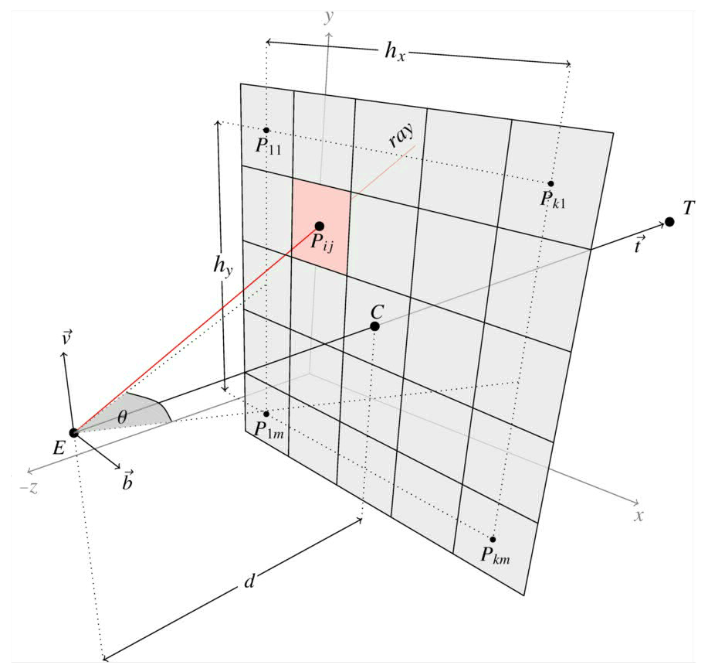
In ray-tracing technique critical point is to calculate rays which came out from eye $E$ to target $T$ through pixel $P_{ij}$ on viewport. The "viewport" is represented as rectangle divided to square pixels - this rectangle is perpendicular to line which go through points $E$, $C$ (viewport center) and $T$. The ray (red line on image) is represented by point $E$ and unit vector $r_{ij}$ (not shown in picture but it lay on red line) - below is picture which show "geometry" - but what are the formulas to calculate $r_{ij}$?

The given input values are:

  • eye position $E$,
  • target position $T$,
  • field of view $\theta$ (angle, for human eye $\approx 90^\circ$),
  • number of square pixels $k$ (horizontal direction) and $m$ (vertical direction).
  • $i,j$ processed pixel indexes where $1\leq i\leq k$ and $1\leq j\leq m$
  • we also know vertical $w$ vector usually equal to $w=[wx,wy,wz]=[0,1,0]$ (not shown on picture) which indicate where is up and where is down

The orthogonal vectors $v$ and $b$ (and $t$) on picture are determined by $w$ and $t=T-E$ and maybe will useful in $r_{ij}$ calculations. The $d$ and pixel size is arbitrary and don't change the result because of fixed $\theta$.

Question: How to calculate unit vector $r_{ij}$ knowing input values described above?

enter image description here

$\endgroup$
2
  • $\begingroup$ What kind of program did you use to render this graphic? $\endgroup$
    – Tooster
    Commented Aug 27, 2023 at 9:23
  • 1
    $\begingroup$ @Tooster latex PGF/TikZ $\endgroup$ Commented Aug 27, 2023 at 20:39

3 Answers 3

6
$\begingroup$

Read up on the basics for ray-tracing here,

Usually we don't mess up with viewports and stuff in raytracing, So I'm just telling you for the case where viewport equals the Image Width and Height.

There are two cases when the field of view changes. Either you move the image plane back and forth or you increase the size. We choose to change $d$ ( former approach).

Calculating ray is simple when the camera is aligned with the world, all you have to do is

$d = 1/tan(\theta_{fov}/2))$

$P_x = P_x + 0.5$
$P_y = P_y + 0.5$

$aspect\_ratio = width/height$

$ray.dir.x = aspect\_ratio *(2*P_x/width) -1$

$ray.dir.y = (2*P_y/height) - 1$

$ray.dir.z = d$

The $Z$ coordinate should be negative or positive depending on whether you are using a right handed or left handed coordinate system. $P_x$ and $P_y$ are pixel coordinates offset by $0.5$ to get the center of the pixel.

The process is simple. You first map your image to NDC space (-1, 1). However to account for non-square images we scale the $X$ coordinate by Aspect ratio so it's $[-a, a]$ in $X$ and $[-1,1]$ in Y. The ray's direction through the pixel is then given by above formulas. You might have to flip the $Y$ coordinate if the image coordinate's origin is top left instead of bottom left.

Note however the link bases all their coordinate systems and space names on RenderMan which is quite different from OpenGL. For camera that isn't aligned with the world coordinate you have to multiply by the transformation matrix as described by bernie in his answer

EDIT:-

First of all let's clear up on -ve and +ve $d$. For right handed coordinate systems you always set $ray.dir.z = -d$ and for left handed $ray.dir.z = d$ This is because in camera space there is no concept of half rays having -ve Z and half +ve, that happens in world space. When you multiply by the transformation matrix it takes care of these cases for you since the transformation matrix is designed keeping in mind whether you are working on a left handed or right handed system. I know i said that you always set it to +ve $d$ but i was wrong in the comments, sorry.

Now coming to your other question. You need the vectors $b,v,t$ and $E$ for creating a transformation matrix. Usually in raytracing you create your camera and initialize its transformation matrix to the standard case (aligned with world space) Then when you move your mouse or something you create a respective rotation matrix and transform the original camera matrix to keep up with these changes. Then when calculating the ray you multiply it as I said above to get ray direction easily. So you probably need to manage your own Camera first.

Since you aren't managing in this case you explicitly need to find these vectors. You mention you have the $w$ vector which is global up. $t$ is easy to find as you say

$t = T-E$

However remember this is the viewing direction not the basis vector. For right handed coordinate systems, the basis vector for $Z$ is $-V_{dir}$

For $b$ which is Camera's right vector. You do, $ w \times t = b$

This gets you the Camera's up vector. Then you do,

$ t \times b = v$

to get the Camera's up vector. This works as long as $t$ doesn't equal $w$ which is the global up.

So after you have these you can create a camera transformation matrix with $c_1, c_2, c_3, c_4 = b, v, t, E$ respectively.

EDIT2:- Instead of following above approach you can also do Gram-Schmidt orthogonalization which is more standard in this case. Using this you get the Camera's up vector $v$ as

$v = w - (t.w)\hat{t}$

Then side vector as,

$b = v \times t$

For right handed systems. For left handed systems you need to change the ordering of cross products.
$\endgroup$
1
3
$\begingroup$

First, the viewport size: $$h_x = 2*d*tan(\theta_x/2)$$ $$h_y = 2*d*tan(\theta_y/2)$$

Each pixel (from your diagram) has the following size in the eye coordinate system: $$W = h_x / (k-1)$$ $$H = h_y / (m-1)$$

Note that usually the field of view encompasses whole pixels and doesn't stop at the center of the edge pixels like your diagram shows.

If $P_c$ is the viewport center in pixel coordinates, let:

$$\vec {P'_{ij}} = P_{ij} - P_c$$

Therefore, $P_{ij}$ in eye space becomes: $$ [P_{ij}]_e = \begin{pmatrix} (W, 0) * \vec {P'_{ij}} \\ (0, H) * \vec {P'_{ij}} \\ d \\ \end{pmatrix} $$

and in the standard base: $$[P_{ij}]_{std} = (\vec b, \vec v, \vec t) * [P_{ij}]_e$$

Normalize the one in the base you want to get $r_{ij}$.

Original answer

The last time I wanted to go from window coordinates (pixels) to eye coordinates, I followed the steps outlined here in the OpenGL wiki. Once you have the eye coordinates, you can just normalize the vector to obtain $r_{ij}$.

$\endgroup$
6
  • $\begingroup$ The eye position is known, but not the pixel's position in the eye coordinate system which is what you're looking for. $\endgroup$
    – bernie
    Commented Jan 18, 2019 at 9:54
  • $\begingroup$ ok but the problem is that I not use OpenGL explicity and don't have that stuff described in wiki likes clip space, projection matrix etc. :( I have only simplified javascript used by gpu.js library which allows me to perform any calculations on gpu - the kernel function (fragment shader written in simplidied javascript) takes on input i,j as this.thread.x and this.thread.y coordinates and thats all (plus input parameters which I describe on question). $\endgroup$ Commented Jan 18, 2019 at 9:59
  • $\begingroup$ Can you explain what is the meaning of $(W, 0) * \vec {P'_{ij}}$ and $[P_{ij}]_e$ and $(\vec b, \vec v, \vec t)$ and $[P_{ij}]_{std}$ (and how to get $r_{ij}$ from it) because I don't understand notation $\endgroup$ Commented Jan 18, 2019 at 12:36
  • $\begingroup$ Sorry that's just too much to explain. $(W, 0) * \vec {P'_{ij}}$ means multiply the x component of $\vec {P'_{ij}}$ by W. Read up on linear algebra and change of basis for more information. Also, you did not specify in which basis you want $r_[ij]$. $\endgroup$
    – bernie
    Commented Jan 18, 2019 at 13:24
  • $\begingroup$ you not explain meaning of all symbols - sorry I dont understant. I dont indroduce any basis - because I need result in natural/canonical basis $\left[\begin{matrix} 1 &0 &0 \\ 0 &1 &0 \\ 0 &0 &1\end{matrix}\right]$ - which means that $E, T, w$ and $r_{ij}$ shoud not be transformed to any basis $\endgroup$ Commented Jan 18, 2019 at 13:40
0
$\begingroup$

GPU friendly - full formulas

IDEA: lets find position of center of each pixel $P_{ij}$ which allows us to easily find ray which starts at $E$ and go thought that pixel. To do it we find first $P_{1m}$ and find others by move on vievports plane.

ASSUMPTION: Below we introduce formulas which includes distance $d$ between eye and viewport however this value will be reduced during ray $r_{ij}$ normalization (so you might as well accept that $d=1$ and remove it from calculations).

PRECALCULATIONS: First we calculate normalized vectors $v_n, b_n$ from picutre (which are parallel to viewport plane and give as direction for shifting)

$$t = T-E, \qquad b = w\times t $$

$$ t_n = \frac{t}{||t||}, \qquad b_n = \frac{b}{||b||}, \qquad v_n = t_n\times b_n \\ $$

notice: $C=E+t_nd$, then we calculate viewport size divided by 2 and including aspect ratio $\frac{m}{k}$

$$g_x=\frac{h_x}{2} =d \tan \frac{\theta}{2}, \qquad g_y =\frac{h_y}{2} = g_x \frac{m}{k}$$

and then we calculate shifting vectors $q_x,q_y$ on viewport $x,y$ direction and viewport left upper pixel

$$ q_x = \frac{2g_x}{k-1}b_n, \qquad q_y = \frac{2g_y}{m-1}v_n, \qquad p_{1m} = t_n d - g_xb_n - g_yv_n$$

CALCULATIONS: notice that $P_{ij} = E + p_{ij}$ and ray $R_{ij} = P_{ij} -E = p_{ij}$ so normalized ray $r_{ij}$ is

$$ p_{ij} = p_{1m} + q_x(i-1) + q_y(j-1)$$ $$ r_{ij} = \frac{p_{ij}}{||p_{ij}||} $$

TEST: above formulas wast tested HERE (works in browser)

SUMMARY: The above form is convenient to use it in shaders where in shader kernel we perform only final calculation based on prcarculated $q_x,q_y$ and $p_{1m}$. Wiki here.

$\endgroup$
0

Your Answer

By clicking “Post Your Answer”, you agree to our terms of service and acknowledge you have read our privacy policy.

Not the answer you're looking for? Browse other questions tagged or ask your own question.