9
$\begingroup$

When reducing color depth and dithering with a 2 bit noise (with n=]0.5,1.5[ and output=floor(input*(2^bits-1) + n)), the ends of the value range (inputs 0.0 and 1.0) are noisy. It would be desirable to have them to be solid color.

Example: https://www.shadertoy.com/view/llsfz4

Noise gradient (above is screenshot of the shadertoy, picturing a gradient and both ends which should be solid white and black respectively, but are noisy instead)

The problem can be of course solved by just compressing the value range so that the ends get always rounded to single values. This feels bit of a hack though, and I'm wondering if there's a way to implement this "properly"?

$\endgroup$
7
  • $\begingroup$ For some reason the shadertoy did not run on my browser. Could you post a/some simple image(s) to demonstrate what you mean? $\endgroup$
    – Simon F
    Commented Nov 23, 2017 at 15:20
  • 1
    $\begingroup$ Shouldn't it be more like n=]-1, 1[? $\endgroup$
    – JarkkoL
    Commented Nov 24, 2017 at 6:35
  • $\begingroup$ @JarkkoL Well the formula for converting floating point to integer is output=floor(input * intmax + n), where n=0.5 without noise, because you want (for example) >=0.5 to round up, but <0.5 down. That's why the noise is "centered" at 0.5. $\endgroup$ Commented Dec 1, 2017 at 17:12
  • $\begingroup$ @SimonF added image of the shadertoy $\endgroup$ Commented Dec 1, 2017 at 20:41
  • 1
    $\begingroup$ It seems you were truncating the output rather than rounding it (like GPUs do) - rounding instead, at least you get proper whites: shadertoy.com/view/MlsfD7 (image: i.sstatic.net/kxQWl.png ) $\endgroup$ Commented Dec 1, 2017 at 20:49

3 Answers 3

9
$\begingroup$

TL;DR: 2*1LSB triangular-pdf dithering breaks in edgecases at 0 and 1 due to clamping. A solution is to lerp to a 1bit uniform dither in those edgecases.

I am adding a second answer, seeing as this turned out a bit more complicated than I originally thought. It appears this issue has been a "TODO: needs clamping?" in my code since I switched from normalized to triangular dithering... in 2012. Feels good to finally look at it :) Full code for solution / images used throughout the post: https://www.shadertoy.com/view/llXfzS

First of all, here is the problem we are looking at, when quantizing a signal to 3bits with 2*1LSB triangular-pdf dithering:

outputs - essentially what hotmultimedia showed.

Increasing contrast, the effect described in the question becomes apparent: The output does not average to black/white in the edgecases (and actually extends well beyond 0/1 before doing so).
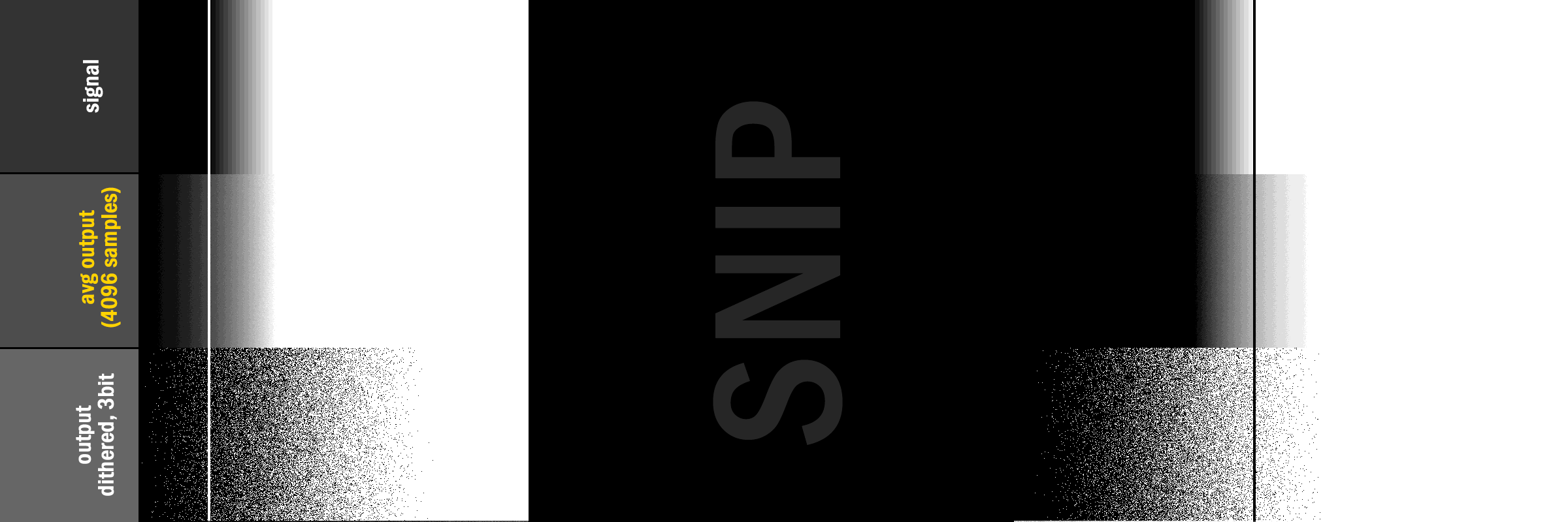
enter image description here

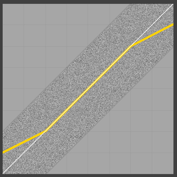
Looking at a graph provides a bit more insight:

enter image description here (grey lines mark 0/1, also in grey is the signal we are trying to output, yellow-line is average of dithered/quantized output, red is the error (signal-average)).

Interestingly, not only is the average output not 0/1 at the limits, it is also not linear (likely due to the triangular pdf of the noise). Looking at the lower end, it makes intuitive sense why the output diverges: As the dithered signal starts to include negative values, the clamping-on-output changes the value of the lower dithered parts of the output (ie the negative values), thereby increasing the value of the average. An illustration appears to be in order (uniform, symmetric 2LSB dither, average still in yellow):
enter image description here

Now, if we just use a 1LSB normalized dither, there are no issues at the edges-cases at all, but then of course we lose the nice properties of triangular dithering (see e.g. this presentation).
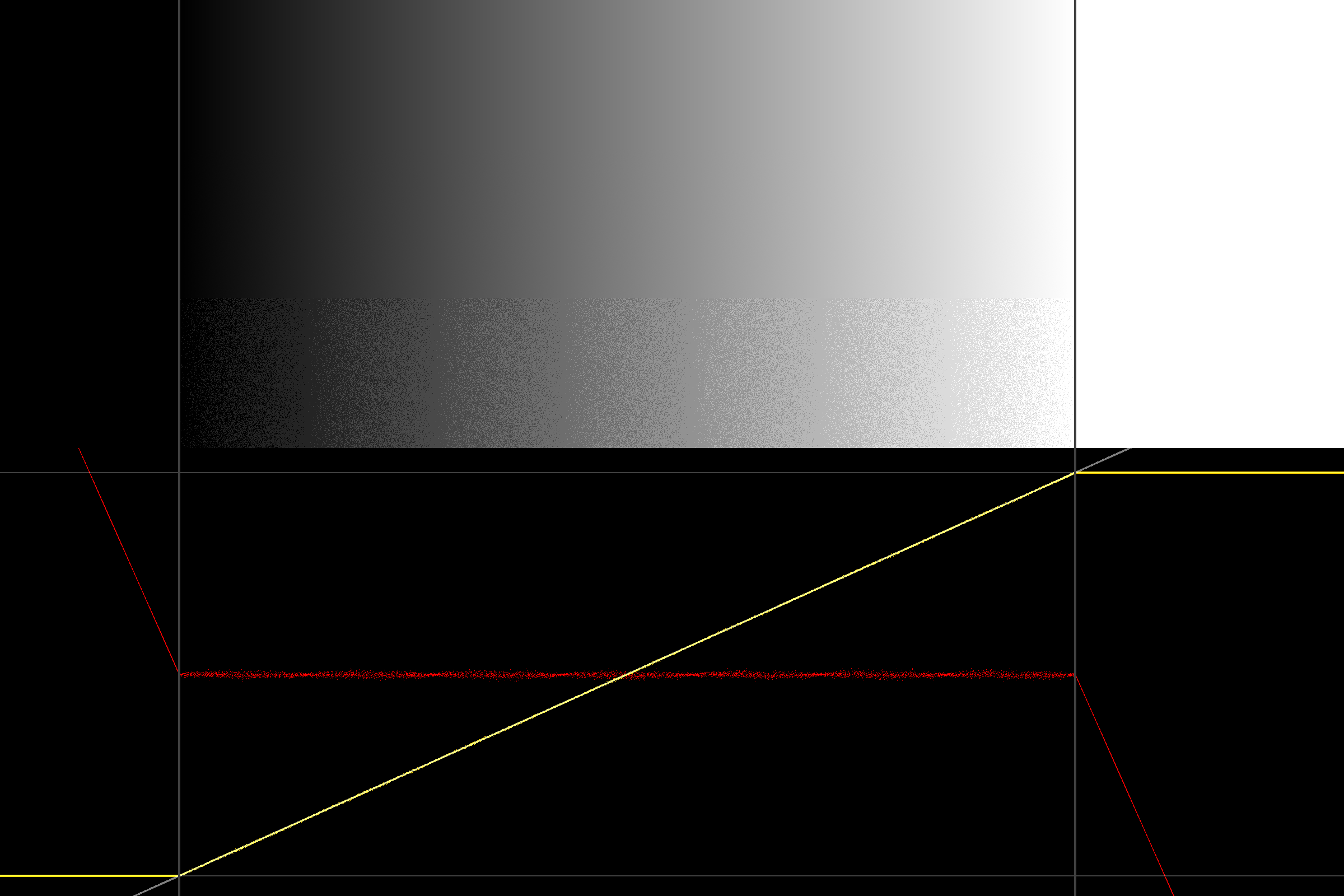
enter image description here

A (pragmatic, empirical) solution (hack) then, is to revert to [-0.5;0.5[ uniform dithering for the edgecase:

float dithertri = (rnd.x + rnd.y - 1.0); //note: symmetric, triangular dither, [-1;1[
float dithernorm = rnd.x - 0.5; //note: symmetric, uniform dither [-0.5;0.5[

float sizt_lo = clamp( v/(0.5/7.0), 0.0, 1.0 );
float sizt_hi = 1.0 - clamp( (v-6.5/7.0)/(1.0-6.5/7.0), 0.0, 1.0 );

dither = lerp( dithernorm, dithertri, min(sizt_lo, sizt_hi) );

Which fixes the edgecases while keeping the triangular dithering intact for the remaining range:
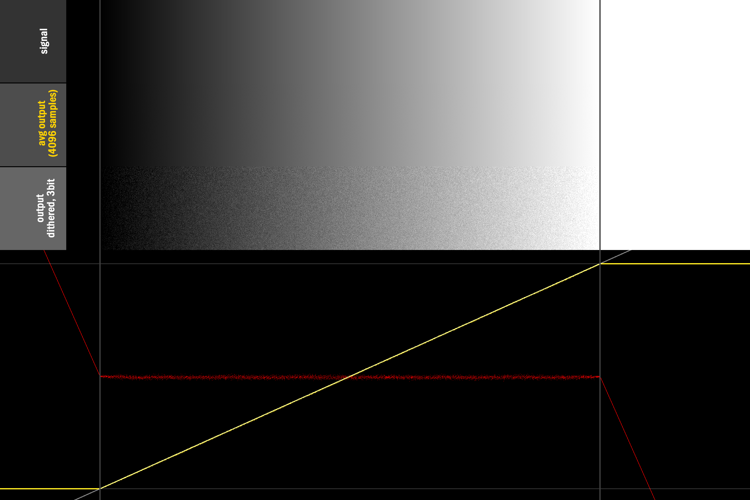
enter image description here

So to not answer your question: I do not know if there is a more mathematically solid solution, and am equally keen to know what Masters of Past have done :) Until then, at least we have this horrific hack to keep our code functioning.

EDIT
I should probably cover the workaround-suggestion given in The Question, on simply compressing the signal. Because the average is not linear in the edgecases, simply compressing the input-signal does not produce a perfect result - though it does fix the endpoints: enter image description here

References

$\endgroup$
4
  • $\begingroup$ It's amazing that the lerp at the edges gives a perfect looking result. I would expect at least a little deviation :P $\endgroup$
    – Alan Wolfe
    Commented Dec 4, 2017 at 3:15
  • $\begingroup$ Yea, I was positively surprised too :) I believe it works because we are scaling down the dither-magnitude linearly, at the same rate the signal is decreasing. So then at least the scale matches... but I agree that it is interesting that directly blending the distributions appears to have no negative side-effects. $\endgroup$ Commented Dec 17, 2017 at 13:16
  • $\begingroup$ @MikkelGjoel Unfortunately, your belief is incorrect due to a bug in your code. You re-used the same RNG for both dithertri and dithernorm instead of an independent one. Once you work through all the math and cancel all the terms, you'll find that you're not lerping at all! Instead, the code acts like a hard cutoff at v < 0.5 / depth || v > 1 - 0.5/depth, instantly switching to the uniform distribution there. Not that it takes away from the nice dithering you have, it's just needlessly complicated. Fixing the bug is actually bad, you'll end up with a worse dither. Just use a hard cutoff. $\endgroup$
    – orlp
    Commented Apr 19, 2019 at 7:10
  • $\begingroup$ After digging even deeper I've found another issue in your shadertoy where you don't do gamma-correcting while averaging samples (you average in sRGB space which isn't linear). If you handle gamma appropriately we find that unfortunately we are not done yet. We must shape our noise to deal with the gamma correction. Here is a shadertoy displaying the issue: shadertoy.com/view/3tf3Dn. I've tried a bunch of things and couldn't get it to work, so I posted a question here: computergraphics.stackexchange.com/questions/8793/…. $\endgroup$
    – orlp
    Commented Apr 23, 2019 at 1:52
3
$\begingroup$

I am not sure I can fully answer your question, but I will add some thoughts and maybe we can arrive at an answer together :)

First, the foundation of the question is a bit unclear to me: Why do you consider it desirable to have clean black/white when every other color has noise? The ideal result after dithering is your original signal with entirely uniform noise. If black and white are different, your noise becomes signal-dependant (which might be fine though, since it happens where colors are clamped anyway).

That said, there are situations, where having noise in either whites or blacks does pose an issue (I am not aware of usecases that require both black and white to simultaneously be "clean"): When rendering an additively blended particle as a quad with a texture, you do not want noise added in the entire quad, as that would show outside the texture as well. One solution is to offset the noise, so rather than adding [-0.5;1.5[ you add [-2.0;0.0[ (ie subtract 2bits of noise). This is quite an empirical solution, but I am not aware of a more correct approach. Thinking about it, you likely also want to boost your signal to compensate for the lost intensity...

Somewhat related, Timothy Lottes did a GDC talk on shaping noise to the parts of the spectrum where it is most needed, reducing noise in the bright end of the spectrum: http://32ipi028l5q82yhj72224m8j-wpengine.netdna-ssl.com/wp-content/uploads/2016/03/GdcVdrLottes.pdf

$\endgroup$
1
  • $\begingroup$ (sorry I hit enter accidentally, and edit time limit expired) The usecase in the example is one those situations where it would matter: rendering a floating point grayscale image on a 3-bit display device. Here the intensity changes greatly by just changing the LSB. I'm trying to understand if there is the any "correct way" to have end values map to solid colors, like compressing the value range and have the end values saturate. And what is the mathematical explanation of that? In the example formula, input value of 1.0 doesn't produce output that averages to 7, and that's what bothers me. $\endgroup$ Commented Dec 1, 2017 at 23:03
1
$\begingroup$

I've simplified Mikkel Gjoel's idea of dithering with triangular noise to a simple function that only needs a single RNG call. I've stripped away all unecessary bits so it should be pretty readable and understandable what's going on:

// Dithers and quantizes color value c in [0, 1] to the given color depth.
// It's expected that rng contains a uniform random variable on [0, 1].
uint dither_quantize(float c, uint depth, float rng) {
    float cmax = float(depth) - 1.0;
    float ci = c * cmax;

    float d;
    if (ci < 0.5 || ci >= cmax - 0.5) {
        // Uniform distribution on [-0.5, 0.5] for edges.
        d = rng - 0.5;
    } else {
        // Symmetric triangular distribution on [-1, 1].
        d = (rng < 0.5) ? sqrt(2.0 * rng) - 1.0 : 1.0 - sqrt(2.0 - 2.0*rng);
    }

    return uint(clamp(ci + d + 0.5, 0.0, cmax));
}

For the idea and context I'll refer you to Mikkel Gjoel's answer.

$\endgroup$

Your Answer

By clicking “Post Your Answer”, you agree to our terms of service and acknowledge you have read our privacy policy.

Not the answer you're looking for? Browse other questions tagged or ask your own question.