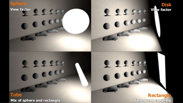
I'm going to provide the simple/naive/brute force answer to this question, which does work, and gives accurate results.
There are better answers however, which make the rendering converge faster with fewer samples, but uses more advanced math. I'm hoping someone else will provide an answer along those lines.
The simple answer is this:
Area lights are just geometry which have an emissive value.
To add support for emissive values to path tracing is pretty easy luckily.
As you know, the amount of light heading towards a pixel is the amount of light leaving the surface that a ray down that pixel would intersect.
That is calculated recursively by seeing how much light is hitting that point, integrating the BRDF, multiplying by the cosine and all that jazz.
Emissive lighting is just added to that result. So, whatever you have now as "outgoing light" from a surface, just add to it the emissive color of that surface. (You could also optionally do something similar to texture mapping and have emissive values vary over the object, possibly based on a texture).
That's all there is to it, it's very simple and easy.
In the rendering equation below, $L_e(\omega_o)$ represents the emissive term (that's what the e stands for, emissive), and the rest of the equation is the light integrated over the hemisphere. You can see that you just add the emissive to the result you return as your outgoing light from a point ($L_o( \omega_o)$) to apply that emissive lighting.
$L_o( \omega_o)= L_e(\omega_o)+\int_{\Omega}{f(\omega_i, \omega_o)L_i(\omega_i)(\omega_i \cdot n)\mathrm{d}\omega_i}$
You can read more about a simple path tracer with area lights at this link, which also has commented C++ source code.
http://blog.demofox.org/2016/09/21/path-tracing-getting-started-with-diffuse-and-emissive/


