3
$\begingroup$

I am trying to write a ray-tracer. The lighting part is proving to work but not accurately. To debug I simplified the scene to a single sphere centered at the origin with a radius of 1 and a point light shining from above (0, 2, 0). The camera is at (0, 0, 4).

ambient 0.2 0.2 0.2 specular 0 0 0 shininess 1 emission 0 0 0 diffuse 0 1 1

The image I'm rendering seems wrong - should its cutoff be lower closer to the equator of the sphere?

Any help would be appreciated.enter image description here

$\endgroup$

2 Answers 2

5
$\begingroup$

Some elementary trigonometry tells you what to expect from this situation.

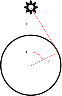
Diagram of the situation

The angle to see the shadow terminator is marked on the diagram, and a use of SOHCAHTOA tells you it's $\cos^{-1}\tfrac{1}{2} = 60^\circ$. Yours looks higher than that so your intuition seems correct. Stepping through the lighting code will help you see where it's going wrong, and you should consider writing unit tests for it, so that it's easier to provoke bugs like this in isolation.

Something else you might try to help narrow down the problem space is replacing the diffuse calculation with 1 iff $L.N > 0$ (i.e. if the light is in front of the surface), 0 o/w. That will give you a sharp line instead of a gradient, and if that sharp line is in the wrong place, you know the input vectors are wrong. If it's in the right place, the problem is in the diffuse shader itself.

$\endgroup$
2
  • $\begingroup$ Just wanted to ask, wouldn't the shadow terminator also depend on the intensity of the light? I mean theoretically no, but practically speaking if there is a very dim light we wouldn't be able to perceive the slightly lit up surface above the terminator making it look like the terminator was way up ? $\endgroup$ Commented Aug 22, 2019 at 6:00
  • 1
    $\begingroup$ @gallickgunner That's true. You should be able to tell the difference though, because normally you only get the $L.N$ diffuse contribution approaching zero towards the terminator (or whatever BRDF you use), whereas in this case, you'd also see the $\tfrac{1}{r^2}$ fall-off of the light intensity. You could work out the expected pixel values on the back of an envelope if you could be bothered, but it's probably easier to just debug the code. $\endgroup$
    – Dan Hulme
    Commented Aug 22, 2019 at 9:25
0
$\begingroup$

Thanks so much for everyone's replies. It really helped to see any reply that kind of encouraged me to continue.

So after some hours of working out the issue it turns out this is correct on the sphere. The above image is correct. As Dan kindly pointed out and as I later drew it out on paper and tried lights of different heights, the higher the light, the lower the cutoff. Because the light was so close to the sphere only its top was intensely illuminated.

The thing I had gotten incorrect were actually the ellipses normal transforms, which I didn't include in the post because I thought it was more complex, get the basics right first. So it turns out I had to create a different stack to store the non-uniform transforms as it was being read from the file so that the ellipses' normals could be transformed correctly.

So lesson learned - understand all the cases before implementing them.

But I really appreciate this platform! Thanks and cheers to all

$\endgroup$

Your Answer

By clicking “Post Your Answer”, you agree to our terms of service and acknowledge you have read our privacy policy.

Not the answer you're looking for? Browse other questions tagged or ask your own question.