12
$\begingroup$

I just implemented some interpolated texture sampling by sampling the 4x4 nearest pixels then doing Lagrange interpolation across the x axis to get four values to use Lagrange interpolation on across the y axis.

Is this the same as bicubic interpolation or is it different? Or are there different kinds of bicubic interpolation, and this is just one of them perhaps?

Webgl Shadertoy implementation here and relevant GLSL (WebGL) code below: https://www.shadertoy.com/view/MllSzX

Thanks!

float c_textureSize = 64.0;

float c_onePixel = 1.0 / c_textureSize;
float c_twoPixels = 2.0 / c_textureSize;

float c_x0 = -1.0;
float c_x1 =  0.0;
float c_x2 =  1.0;
float c_x3 =  2.0;

//=======================================================================================
vec3 CubicLagrange (vec3 A, vec3 B, vec3 C, vec3 D, float t)
{
    return
        A * 
        (
            (t - c_x1) / (c_x0 - c_x1) * 
            (t - c_x2) / (c_x0 - c_x2) *
            (t - c_x3) / (c_x0 - c_x3)
        ) +
        B * 
        (
            (t - c_x0) / (c_x1 - c_x0) * 
            (t - c_x2) / (c_x1 - c_x2) *
            (t - c_x3) / (c_x1 - c_x3)
        ) +
        C * 
        (
            (t - c_x0) / (c_x2 - c_x0) * 
            (t - c_x1) / (c_x2 - c_x1) *
            (t - c_x3) / (c_x2 - c_x3)
        ) +       
        D * 
        (
            (t - c_x0) / (c_x3 - c_x0) * 
            (t - c_x1) / (c_x3 - c_x1) *
            (t - c_x2) / (c_x3 - c_x2)
        );
}

//=======================================================================================
vec3 BicubicTextureSample (vec2 P)
{
    vec2 pixel = P * c_textureSize + 0.5;

    vec2 frac = fract(pixel);
    pixel = floor(pixel) / c_textureSize - vec2(c_onePixel/2.0);

    vec3 C00 = texture2D(iChannel0, pixel + vec2(-c_onePixel ,-c_onePixel)).rgb;
    vec3 C10 = texture2D(iChannel0, pixel + vec2( 0.0        ,-c_onePixel)).rgb;
    vec3 C20 = texture2D(iChannel0, pixel + vec2( c_onePixel ,-c_onePixel)).rgb;
    vec3 C30 = texture2D(iChannel0, pixel + vec2( c_twoPixels,-c_onePixel)).rgb;

    vec3 C01 = texture2D(iChannel0, pixel + vec2(-c_onePixel , 0.0)).rgb;
    vec3 C11 = texture2D(iChannel0, pixel + vec2( 0.0        , 0.0)).rgb;
    vec3 C21 = texture2D(iChannel0, pixel + vec2( c_onePixel , 0.0)).rgb;
    vec3 C31 = texture2D(iChannel0, pixel + vec2( c_twoPixels, 0.0)).rgb;    

    vec3 C02 = texture2D(iChannel0, pixel + vec2(-c_onePixel , c_onePixel)).rgb;
    vec3 C12 = texture2D(iChannel0, pixel + vec2( 0.0        , c_onePixel)).rgb;
    vec3 C22 = texture2D(iChannel0, pixel + vec2( c_onePixel , c_onePixel)).rgb;
    vec3 C32 = texture2D(iChannel0, pixel + vec2( c_twoPixels, c_onePixel)).rgb;    

    vec3 C03 = texture2D(iChannel0, pixel + vec2(-c_onePixel , c_twoPixels)).rgb;
    vec3 C13 = texture2D(iChannel0, pixel + vec2( 0.0        , c_twoPixels)).rgb;
    vec3 C23 = texture2D(iChannel0, pixel + vec2( c_onePixel , c_twoPixels)).rgb;
    vec3 C33 = texture2D(iChannel0, pixel + vec2( c_twoPixels, c_twoPixels)).rgb;    

    vec3 CP0X = CubicLagrange(C00, C10, C20, C30, frac.x);
    vec3 CP1X = CubicLagrange(C01, C11, C21, C31, frac.x);
    vec3 CP2X = CubicLagrange(C02, C12, C22, C32, frac.x);
    vec3 CP3X = CubicLagrange(C03, C13, C23, C33, frac.x);

    return CubicLagrange(CP0X, CP1X, CP2X, CP3X, frac.y);
}
$\endgroup$
4
  • 2
    $\begingroup$ You could post the relevant shader code here in case of bitrot, no? $\endgroup$
    – joojaa
    Commented Aug 4, 2015 at 18:17
  • 1
    $\begingroup$ we should have some prettier code markup for shader code, i'll post on meta if someone hasn't beaten me to it! $\endgroup$
    – Alan Wolfe
    Commented Aug 4, 2015 at 18:21
  • $\begingroup$ Is that a specific shader language not available in the list of languages covered by our syntax highlighting? $\endgroup$ Commented Aug 5, 2015 at 22:24
  • $\begingroup$ I'm not sure. It's just GLSL (from webgl to be exact!). I just did 4 spaces before each line of code, not sure if there's a better way to mark it up... $\endgroup$
    – Alan Wolfe
    Commented Aug 5, 2015 at 22:37

1 Answer 1

8
$\begingroup$

It turns out that no, while you can use bicubic Lagrange interpolation for bicubic texture sampling, it isn't the highest quality option, and probably not actually likely to be used.

Cubic hermite splines are a better tool for the job.

Lagrange interpolation will make a curve that passes through the data points, thus preserving C0 continuity, but hermite splines preserve the derivatives at the edges while also passing through the data points, thus preserving C1 continuity and looking much better.

This question has some great info on cubic hermite splines: https://dsp.stackexchange.com/questions/18265/bicubic-interpolation

Here is the cubic hermite version of the code I posted in the question:

//=======================================================================================
vec3 CubicHermite (vec3 A, vec3 B, vec3 C, vec3 D, float t)
{
    float t2 = t*t;
    float t3 = t*t*t;
    vec3 a = -A/2.0 + (3.0*B)/2.0 - (3.0*C)/2.0 + D/2.0;
    vec3 b = A - (5.0*B)/2.0 + 2.0*C - D / 2.0;
    vec3 c = -A/2.0 + C/2.0;
    vec3 d = B;

    return a*t3 + b*t2 + c*t + d;
}

//=======================================================================================
vec3 BicubicHermiteTextureSample (vec2 P)
{
    vec2 pixel = P * c_textureSize + 0.5;

    vec2 frac = fract(pixel);
    pixel = floor(pixel) / c_textureSize - vec2(c_onePixel/2.0);

    vec3 C00 = texture2D(iChannel0, pixel + vec2(-c_onePixel ,-c_onePixel)).rgb;
    vec3 C10 = texture2D(iChannel0, pixel + vec2( 0.0        ,-c_onePixel)).rgb;
    vec3 C20 = texture2D(iChannel0, pixel + vec2( c_onePixel ,-c_onePixel)).rgb;
    vec3 C30 = texture2D(iChannel0, pixel + vec2( c_twoPixels,-c_onePixel)).rgb;

    vec3 C01 = texture2D(iChannel0, pixel + vec2(-c_onePixel , 0.0)).rgb;
    vec3 C11 = texture2D(iChannel0, pixel + vec2( 0.0        , 0.0)).rgb;
    vec3 C21 = texture2D(iChannel0, pixel + vec2( c_onePixel , 0.0)).rgb;
    vec3 C31 = texture2D(iChannel0, pixel + vec2( c_twoPixels, 0.0)).rgb;    

    vec3 C02 = texture2D(iChannel0, pixel + vec2(-c_onePixel , c_onePixel)).rgb;
    vec3 C12 = texture2D(iChannel0, pixel + vec2( 0.0        , c_onePixel)).rgb;
    vec3 C22 = texture2D(iChannel0, pixel + vec2( c_onePixel , c_onePixel)).rgb;
    vec3 C32 = texture2D(iChannel0, pixel + vec2( c_twoPixels, c_onePixel)).rgb;    

    vec3 C03 = texture2D(iChannel0, pixel + vec2(-c_onePixel , c_twoPixels)).rgb;
    vec3 C13 = texture2D(iChannel0, pixel + vec2( 0.0        , c_twoPixels)).rgb;
    vec3 C23 = texture2D(iChannel0, pixel + vec2( c_onePixel , c_twoPixels)).rgb;
    vec3 C33 = texture2D(iChannel0, pixel + vec2( c_twoPixels, c_twoPixels)).rgb;    

    vec3 CP0X = CubicHermite(C00, C10, C20, C30, frac.x);
    vec3 CP1X = CubicHermite(C01, C11, C21, C31, frac.x);
    vec3 CP2X = CubicHermite(C02, C12, C22, C32, frac.x);
    vec3 CP3X = CubicHermite(C03, C13, C23, C33, frac.x);

    return CubicHermite(CP0X, CP1X, CP2X, CP3X, frac.y);
}

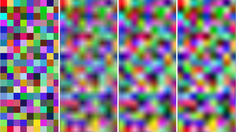
Here is a picture showing the difference between sampling methods. From left to right: Nearest Neighbor, Bilinear, Lagrange Bicubic, Hermite Bicubic

enter image description here

$\endgroup$
8
  • $\begingroup$ Although all cubic splines are, in a sense, equivalent, it's probably conceptually easier to use Catmull-Rom splines. e.g. cs.cmu.edu/~462/projects/assn2/assn2/catmullRom.pdf $\endgroup$
    – Simon F
    Commented Aug 5, 2015 at 14:51
  • $\begingroup$ Do you think the tau parameter helps or hinders in this case? I might be wrong but i feel like catmull rom is too "user defined" (and must be tuned), whereas the hermite spline attempts to just use information from the data that's there. It seems like cubic hermite is closer to a "ground truth", which i guess would be something like an ideal sinc filter. What do you think though? $\endgroup$
    – Alan Wolfe
    Commented Aug 5, 2015 at 15:57
  • $\begingroup$ I don't see how Catmull-Rom is "user defined". Once you have a sequence of 4 contiguous points, P[i-1], P[i], P[i+1], P[i+2] (4x4 for 2D case) the curve segment is defined between P[i] and P[i+1] and is C1 continuous with the neighbouring segments. A sinc filter is fine for audio but not video. See Mitchell & Netravali: cs.utexas.edu/~fussell/courses/cs384g-fall2013/lectures/… IIRC Catmull-Rom is a special case of the family of filters they propose, but I think that filter is an approximating curve so, unlike C-R, might not go through the original points. $\endgroup$
    – Simon F
    Commented Aug 6, 2015 at 9:24
  • $\begingroup$ That's how he hermite spline works except that the catmull rom spline has an additional parameter tau (tension) that is user defined. Also, sinc does apply to video, DSP is DSP :P $\endgroup$
    – Alan Wolfe
    Commented Aug 6, 2015 at 14:04
  • $\begingroup$ I must admit, I've never seen a tension parameter associated with Catmull Rom splines before, but then I've really only learned of them via Foley & van Dam (et al) or, say, Watt & Watt which, AFAICR, make no mention of such. Actually, having said that, given there are four constraints - i.e. the curve has to pass through 2 points and have two defined tangents** at those points and it's a cubic - I'm at a bit of a loss as to how there's any more degrees of freedom to support a tension parameter .... **Unless you mean the tangents can be scaled? $\endgroup$
    – Simon F
    Commented Aug 6, 2015 at 14:29

Your Answer

By clicking “Post Your Answer”, you agree to our terms of service and acknowledge you have read our privacy policy.

Not the answer you're looking for? Browse other questions tagged or ask your own question.