4
$\begingroup$

I am attempting to model a simple graphics pipeline (i.e. Local->Word->View->Screen->2D spaces).

I've been looking at the algorithm required to transform from world to view-space and using the following transformenter image description here

Although I have been using U,V,N,C notation rather than Xc,Yc,Zc,e.

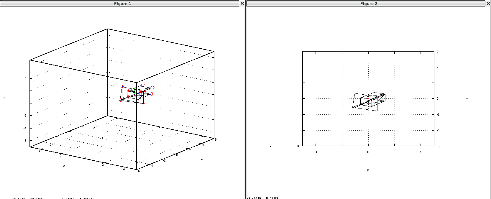
And my matrix transformation at first glance, appears correct: When I plot the vectors onto world space, I get a vector from the camera position to the point we're looking at, and two correctly placed new X and Y vectors (see the left hand image below).

enter image description here

By looking along the line of sight vector (such that it disappears,and the focus & camera points overlap), as in the middle figure, should (I believe?) give an accurate example of what the resultant viewspace transformation should look like, with the green vertical and right-pointing vectors showing the new X & Y vectors.

However - when I actually do the view space transform I don't get the middle figure, instead, the resultant transform seems to be looking at the object from a different position possibly aligned with one of the axes? This is shown in the right hand figure - which is actually looking at the object from a slightly lower perspective

My question is essentially what have I done wrong, or am I misunderstanding both the transform and thus my results?

Thanks very much,

David

UPDATES

After stepping through the code - I discovered that my source book was having me convert the line-of-sight vector to spherical coords and then they were being converted straight back again to create R (viewspace coordination matrix). I've eliminated this redundancy (and potential source of errors) but it hasn't solved the problem...

clear; clc; close all;
%======Create World Space (hard-coded values for demo) ===========
ws_vtx = [0,2,0,2,1,0.5,1.5,0.5,1.5,0.5,1.5,0.5,1.5;
    0,0,0,0,-2,0,0,2,2,0,0,2,2;
    0,0,2,2,1,0.5,0.5,0.5,0.5,1.5,1.5,1.5,1.5];
ws_fcs = [1,2,4,3,3,1,6,6,6,6,7,7,9,8,8,8,10,10;
    2,4,3,1,4,4,9,8,7,11,9,13,8,12,10,6,11,13;
    5,5,5,5,1,2,7,9,11,10,13,11,13,13,12,10,13,12];
%==================Create view matrix===================
focus = [1.5,0,1.5]; %The point we're looking at
Cx = 3; Cy = -3; Cz = 3; %Position of camera
Vspec = [0;0;1]; %Specified up direction for view space (i.e. camera orientation)
vector = focus - [Cx,Cy,Cz]; %Vector camera to focus point 
p = sqrt(vector(1)^2 + vector(2)^2 + vector(3)^2); %Total magnitude of vector
N = vector'/p;
V = Vspec - cross(cross(Vspec,N),N); %Create new "up" direction
U = cross(N,V); %Create new x-axis
%Create rotational matrix to view space
R= [U(1),U(2),U(3),0; % U is direction of camera space X axis
    V(1),V(2),V(3),0; % V is direction of camera space Y axis
    N(1),N(2),N(3),0;
    0   ,   0,   0,1];
Tr = [1,0,0,-Cx;
      0,1,0,-Cy;
      0,0,1,-Cz;
      0,0,0,  1];
T = R*Tr; %Total view transform = rotation * translation
%============Plot the camera vectors & World Space=================
grid on; hold on; xlabel('x'); ylabel('y'); zlabel('z');
scatter3(Cx,Cy,Cz,'s'); %Plot the camera position
plot3([Cx, Cx+p*N(1)],[Cy, Cy+p*N(2)],[Cz, Cz+p*N(3)],'g'); %Plot camera vectors
plot3([Cx, Cx+V(1)],[Cy, Cy+V(2)],[Cz, Cz+V(3)],'g');
plot3([Cx, Cx+U(1)],[Cy, Cy+U(2)],[Cz, Cz+U(3)],'g');
scatter3(ws_vtx(1,:),ws_vtx(2,:),ws_vtx(3,:)) %Plot all the points
patch('Faces',ws_fcs','Vertices',ws_vtx','Facecolor', 'none');
for i = 1:length(ws_vtx)
    str = sprintf('%d',i);
    text(ws_vtx(1,i),ws_vtx(2,i),ws_vtx(3,i), str,'FontSize',14, 'Color','r');
end
%====================Viewspace Transform===========================
ws_vtx = T*vertcat(ws_vtx,(ones(1,length(ws_vtx)))); %Transform worldspace
ws_vtx = ws_vtx(1:3,:); %Remove homogenous column
position = T*[Cx;Cy;Cz;1]; focus = T*horzcat(focus,1)'; %Transform set points
position = position(1:3,:); focus = focus(1:3,:); %Remove homogenous columns
%================Plot new viewspace===============================
figure(); grid on; hold on; xlabel('x'); ylabel('y'); zlabel('z');
scatter3(position(1),position(2),position(3),'s'); %Plot new camera vectors
scatter3([position(1); position(1)+focus(1)],...
    [position(2); position(2)+focus(2)],[position(3); position(3)+focus(3)],'s');
plot3([position(1), focus(1)],[position(2), focus(2)],[position(3), focus(3)],'g');
patch('Faces',ws_fcs','Vertices',ws_vtx','Facecolor', 'none');
$\endgroup$
2
  • 1
    $\begingroup$ The object in the right hand image does appear to be at a similar angle to the middle image. It's just that the axes are not the same. Is it only the axes you are asking about, or does the object itself have a problem? $\endgroup$ Commented Feb 12, 2016 at 19:20
  • $\begingroup$ It's essentially the axes - I would have thought that the axes should be rotated to look like the central figure. Instead, it's slightly off, as in the right figure $\endgroup$
    – davidhood2
    Commented Feb 12, 2016 at 20:36

2 Answers 2

2
+50
$\begingroup$

Your transform looks correct. To transform from world to eye coordinates, I I always use a "lookat" transform, defined by 3 vectors: $\bf{e}$, $\bf{a}$ and $\bf{u}$; in english, the eye position, the point it's looking at, and an up vector, which must not be in the same direction as $\bf{a} - \bf{e}$ (more specifically, not a multiple of it).

The space is defined using $\bf{z} = {{(\bf{e} - \bf{a})}\over{|\bf{e} - \bf{a}}|}$, which means the negative z axis points in the direction of what I'm looking at (this works well for OpenGL); $\bf{x} = {{\bf{u} \times \bf{z}}\over{|\bf{u} \times \bf{z}|}}$ and $\bf{y} = \bf{z} \times \bf{x}$, which, again, for OpenGL, makes $\bf{x}$ rightward on the screen and $\bf{y}$ upward.

To transform into eye coordinates is a matter of subtracting they eye's position, then projecting into the space defined by the vectors above:

$$\begin{bmatrix} \bf{x}_x & \bf{x}_y & \bf{x}_z & 0 \\ \bf{y}_x & \bf{y}_y & \bf{y}_z & 0 \\ \bf{z}_x & \bf{z}_y & \bf{z}_z & 0 \\ 0 & 0 & 0 & 1 \end{bmatrix}\begin{bmatrix} 1 & 0 & 0 & -\bf{e}_x \\ 0 & 1 & 0 & -\bf{e}_y \\ 0 & 0 & 1 & -\bf{e}_z \\ 0 & 0 & 0 & 1 \end{bmatrix} $$

Which is exactly what you have to begin with.

$\endgroup$
2
  • $\begingroup$ I don't think it is what I had to begin with - although on a brief glance it should seem that e <=> C and x,y,z <=> U,V,N, when I change the code to use your method, the results are starting to seem more intuitively correct! $\endgroup$
    – davidhood2
    Commented Feb 16, 2016 at 10:13
  • 2
    $\begingroup$ In your matrix you have a "c" superscript on the x, y and z components (camera space). I added a description of how to derive the eye local space based on the gluLookat parameters. I think that pyramid in front is pretty confusing; I'd use one box to start with. Try plotting looking down the axi first, make sure you get the correct rectangles. Also, anything that can let you animate changing the parameters will help clear things up immensely. A single wireframe picture is always hard to decode... $\endgroup$
    – user2500
    Commented Feb 16, 2016 at 12:31
4
$\begingroup$

I've done some small changes to how I usually construct my view matrix, here is what I've modified:

// put it after N = ...
U = cross(N, Vspec);
U = U / sqrt(dot(U,U)); % normalize
V = cross(U, N);

Then I also set N vector as -N to R matrix, like this:

R= [U(1),U(2),U(3),0; % U is direction of camera space X axis
    V(1),V(2),V(3),0; % V is direction of camera space Y axis
    -N(1),-N(2),-N(3),0;
    0   ,   0,   0,1];

as shown e.g. in the code for lookAt matrix for OpenGL

Now you can orient your first graph, as if you look through your camera, this will give you a reference of how it should look on the second graph.

Then orient second graph so that you look through -Z axis, Y looks up, and X from left to right. Because your camera view vector is -Z, up is Y and right is X. Once you orient your second graph like this, you'll see that arrow looks identically to the first graph, ray on graph 2 will be drawn as point, because it is directed along -Z (your view direction), and in camera space end and start points will fall on a same pixels (another hint that it is correct).

I've also modified a bit camera pos, view direction and axes (just to make it easier to observe for myself).

Here are the values, that I've used: focus = [1.2,0,1.5]; %The point we're looking at Cx = 3; Cy = -3; Cz = 3; %Position of camera

And for the axes: axis([-5,5,-6,6,-7,7]);

Here is what I've got

I can send you whole code if you need.

$\endgroup$
4
  • $\begingroup$ Wouldn't norm be better at normalizing also you can write R[U, 0; V, 0; -N, 0; 0, 0, 0, 1] $\endgroup$
    – joojaa
    Commented Feb 18, 2016 at 22:23
  • 1
    $\begingroup$ You are right about norm, but sqrt(dot(x,x)), is the same (I do not know octave/matlab very good, so I use math). Regarding matrix - not really, because U, V, N are columns, correct way would be R = [U', 0; V', 0; -N', 0; 0,0,0,1] :-) but I tried to keep original formatting. $\endgroup$
    – alariq
    Commented Feb 18, 2016 at 22:34
  • $\begingroup$ Its the same but really ease of reading would make the code much better... As the original code is a totall mess. Which is mostly why there were not many takers. And the fact that its matlab... $\endgroup$
    – joojaa
    Commented Feb 18, 2016 at 22:47
  • $\begingroup$ Thanks very much - I know the original code is a mess - please accept my apologies! I've tried to do it using only simple matlab functions because I will be porting it to an FPGA (in VHDL) - and am simply trying to model the maths! $\endgroup$
    – davidhood2
    Commented Feb 20, 2016 at 18:26

Your Answer

By clicking “Post Your Answer”, you agree to our terms of service and acknowledge you have read our privacy policy.

Not the answer you're looking for? Browse other questions tagged or ask your own question.