8
$\begingroup$

Lately I've been reading about texture filtering, namely Nearest-neighbor filtering, Bilinear filtering, Trilinear filtering, Anisotropic filtering, MIP maps, RIP Maps and so on.

From a high-level perspective I think I can understand these techniques, how the work and why they exist, with the exception of Anisotropic filtering. Anisotropic filtering is driving me nuts.

I can see the problem of having to texturize a surface that is at an angle relative to the camera, but I don't get how sampling trapezoidal footprints could solve this (although I can see the result). This is probably because I DO NOT understand how the trapezoidal footprint is calculated and how the enclosed telexes are weighted to sample the texture.

This article by Nvidia confuses me even more by using sentences as "when a texel is trapezoidal" or "anisotropic filtering scales either the height or width of a mipmap by a ratio relative to the perspective distortion of the texture". Trapezoidal texel? Scaling a MIPmap? What does this even mean?

Could you help me grasp how AF and AF levels work?

Please note that my goal is NOT to have an OpenGL or DirectX AF implementation, but rather to grasp how AF works from a high-level perspective.

$\endgroup$

2 Answers 2

13
$\begingroup$

To understand the nature of anisotropic filtering, you need to have a firm understanding of what texture mapping really means.

The term "texture mapping" means to assign positions on an object to locations in a texture. This permits the rasterizer/shader to, for each position on the object, fetch the corresponding data from the texture. The traditional method for doing this is to assign each vertex on an object a texture coordinate, which directly maps that position to a location in the texture. The rasterizer will interpolate this texture coordinate across the faces of the various triangles to produce the texture coordinate used to fetch the color from the texture.

Now, let's think about the process of rasterization. How does that work? It takes a triangle and breaks it up into pixel-sized blocks which we will call "fragments". Now, these pixel-sized blocks are pixel-sized relative to the screen.

But these fragments are not pixel-sized relative to the texture. Imagine if our rasterizer generated a texture coordinate for each corner of the fragment. Now imagine drawing those 4 corners, not in screen space, but in texture space. What shape would this be?

Well, that depends on the texture coordinates. That is, it depends on how the texture is mapped to the polygon. For any particular fragment, it might be an axis-aligned square. It might be a non-axis-aligned square. It might be a rectangle. It might be a trapezoid. It might be pretty much any four-sided figure (or at least, convex ones).

If you were doing texture accessing correctly, the way to get the texture color for a fragment would be to figure out what this rectangle is. Then fetch every texel from the texture within that rectangle (using coverage to scale colors that are on the border). Then average them all together. That would be perfect texture mapping.

It would also be exceedingly slow.

In the interest of performance, we instead try to approximate the real answer. We base things on one texture coordinate, rather than the 4 that cover the entire fragment's area in texel space.

Mipmap-based filtering uses lower-resolution images. These images are basically a shortcut for the perfect method, by pre-computing what large blocks of colors would look like when blended together. So when it selects a lower mipmap, it is using pre-computed values where each texel represents an area of the texture.

Anisotropic filtering works by approximating the perfect method (which can, and should, be coupled with mipmapping) through taking up to a fixed number of additional samples. But how does it figure out the area in texel space to fetch from, since it's still only given one texture coordinate?

Basically, it cheats. Because fragment shaders are executed in 2x2 neighboring blocks, it is possible to compute the derivative of any value in the fragment shader in screen-space X and Y. It then uses these derivatives, coupled with the actual texture coordinate, to compute an approximation of what the true fragment's texture footprint would be. And then it performs a number of samples within this area.

Here's a diagram to help explain it:
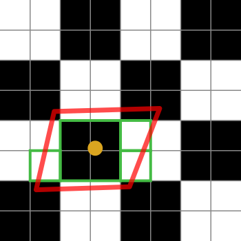
Fragment footprint and anisotropic samples. FYI: if you've seen it before, it's mine.

The black-and-white squares represent our texture. It's just a checkerboard of 2x2 white and black texels.

The orange dot is the texture coordinate for the fragment in question. The red outline is the fragment's footprint, which is centered on the texture coordinate.

The green boxes represent the texels that an anisotropic filtering implementation might access (the details of anisotropic filtering algorithms are platform specific, so I can only explain the general idea).

This particular diagram suggests that an implementation might access 4 texels. Oh yes, the green boxes cover 7 of them, but the green box in the center could fetch from a smaller mipmap, thus fetching the equivalent of 4 texels in one fetch. The implementation would of course weight the average for that fetch by 4 relative to the single texel ones.

If the anisotropic filtering limit was 2 rather than 4 (or higher), then the implementation would pick 2 of those samples to represent the fragment's footprint.

$\endgroup$
4
  • $\begingroup$ Thank you for explaining this and sorry for the delayed answer, but I had to find the time to read this very carefully. I feel like the only paragraph I do not completely understand is the one where you talk about fragment shaders and derivatives. What exactly is derived in screen-space X and Y? Is it the texture coordinate value? $\endgroup$ Commented May 8, 2017 at 13:15
  • $\begingroup$ @NicolaMasotti: "Derivative" is a calculus term. In this case, it is the rate of change of the texture coordinate, across the surface of the triangle, in screen-space X or Y. If you don't know calculus, then I'm not going to be able to explain it to you in a single post. $\endgroup$ Commented May 8, 2017 at 15:52
  • $\begingroup$ Fortunately I know what a derivative is. Is there any place I can look at for the exact math? $\endgroup$ Commented May 8, 2017 at 17:24
  • $\begingroup$ Also, I would propose a couple of changes to your answer, i.e. "it depends on how the polygon is mapped to the texture" instead of "it depends on how the texture is mapped to the polygon". Also, when you say: "using coverage to scale colors that are on the border" do you actually mean "weight colors that are on the border"? $\endgroup$ Commented May 8, 2017 at 17:31
5
$\begingroup$

A few points that you probably already know, but that I just want to put out there for others reading this. Filtering in this case refers to low-pass filtering like you might get from a Gaussian Blur or a box blur. We need to do this because we are taking some media that has high frequencies in it, and rendering it into a smaller space. If we didn't filter it, we would get aliasing artifacts, which would look bad. So we filter out the frequencies that are too high to be accurately reproduced in the scaled version. (And we pass the low frequencies, so we use a "low pass" filter like a blur.)

So let's think about this first from the point of view of a blur. A blur is a type of convolution. We take the convolution kernel and multiply it by all the pixels in an area and then add them together and divide by the weight. That gives us the output of one pixel. Then we move it over and do it again for the next pixel over, and again, etc.

It's really expensive to do it that way, so there's a way to cheat. Some convolution kernels (particularly a Gaussian blur kernel and a box blur kernel) can be separated into a horizontal and vertical pass. You can filter everything with just a horizontal kernel first, then take the result of that and filter it with just a vertical kernel, and the result will be identical to doing the more expensive calculation at every point. Here's an example:

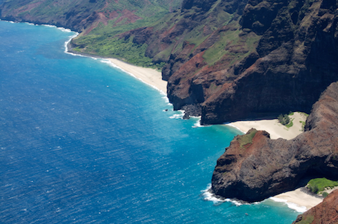
Original:

Hawaii

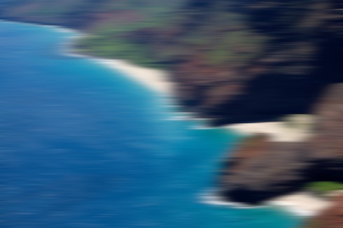
Horizontal Blur:

Hawaii blurred horizontally

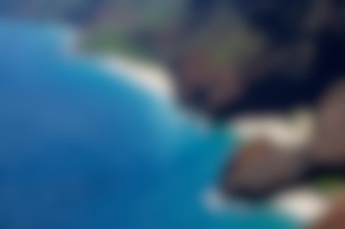
Horizontal followed by Vertical Blur:

Hawaii blurred horizontally and then vertically

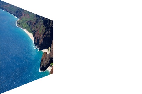
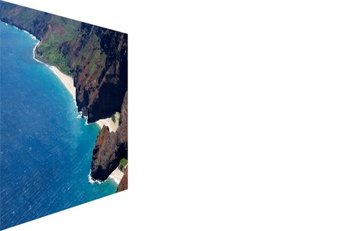
So we can separate the filtering into a vertical and horizontal pass. So what? Well, it turns out that we can do the same thing for spatial transforms. If you think about a perspective rotation, like this:

Hawaii Rotated around Y-axis

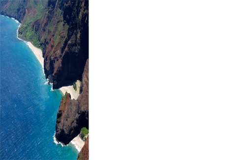
It can be broken down into an X scale:

enter image description here

followed by a scale of each column by a slightly different amount:

Hawaii scaled in X and then proportionally in Y

So now you have 2 different scaling operations. To get the filtering correct for this, you're going to want to filter more heavily in X than in Y, and you're going to want to filter by a different amount for each column. The first column gets no filtering because it's the same size as the original. The second column gets just a little because it's just slightly smaller than the first, etc. The last column gets the most filtering of any column.

The word "anisotropy" comes from the greek "an" meaning "not", "isos" meaning equal, and "tropos" meaning "direction". So it means "not equal in all directions." And that's exactly what we see - the scaling and the filtering are done in different amounts in each direction.

$\endgroup$

Your Answer

By clicking “Post Your Answer”, you agree to our terms of service and acknowledge you have read our privacy policy.

Not the answer you're looking for? Browse other questions tagged or ask your own question.