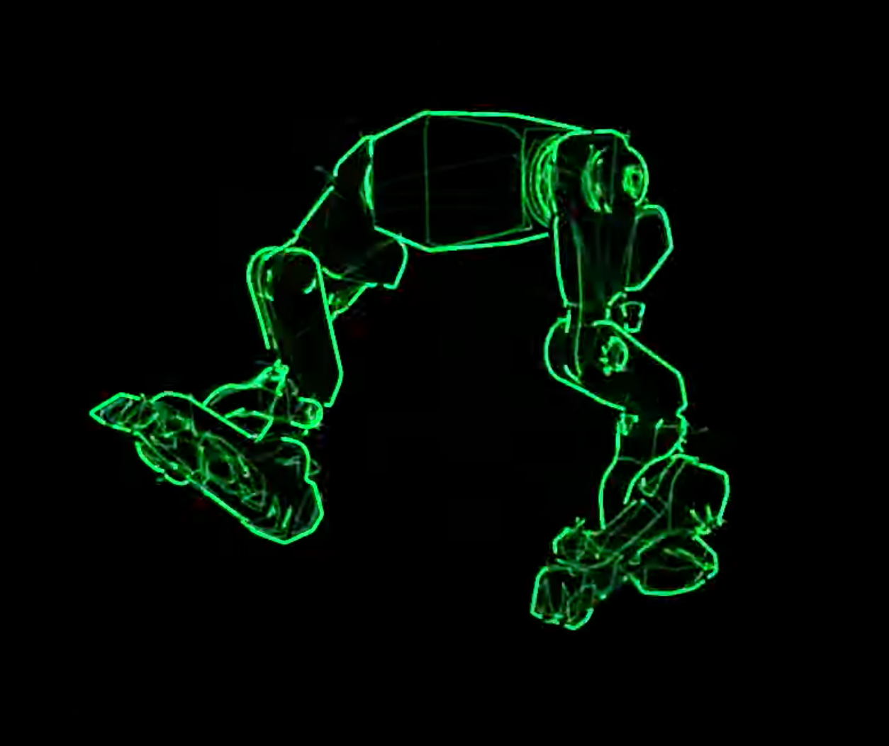
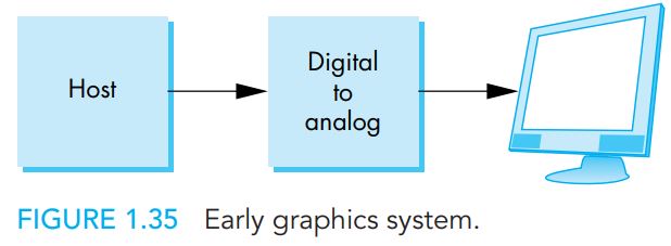
First of all, the type of system they describe is more commonly known today as a vector display. (Until just now, I had never heard it called “calligraphic”.) Looking up information using that name may get you more useful context.
Now as to the principle of operation:
The hardware may be extremely simple. You need:
- Two digital-to-analog converters (DACs), one for X position and one for Y position.
- Two amplifiers of an appropriate type to take those signals to...
- The deflection plates or coils of a CRT.
That's all you need for the fundamental system. Then, to produce a cleaner image, you can optionally add a 3rd digital signal which allows the computer to turn on and off the CRT's beam, or an analog signal to control its brightness.
Now, in order to draw a line, the software will send a series of samples to the DACs, instructing them to change their output analog signals linearly over a short time period. This causes the CRT to sweep the beam across the screen, exciting the phosphor in the shape of a line. Similarly, arbitrary curves can be drawn as long as the computer can calculate a finely-spaced series of points along them.
In order to draw disconnected shapes, you turn off the beam (“blank” it) while you are moving it to the end point of one line to the start point of the new line. (Or, in a simpler system with no blanking, you can move the beam so fast that no visible line is produced — the brightness is inversely proportional to the speed, since the electron gun is firing electrons at the screen at a rate independent of how fast the beam deflection changes. However, this approach is constrained by the bandwidth and/or sample rate of the system.)
Then, in order to keep the image on screen, or animate it, you repeat this entire process, drawing the scene over and over again (just like raster CRTs did). Between drawing cycles, the image is maintained by some combination of the phosphor's glow (it does not darken instantly when the beam leaves, but continues emitting light) and flicker fusion, also known as “persistence of vision”, in the human eye.
The faster the computer can control the DACs, the more content you can put on the screen before the overall frame rate becomes low enough that flicker is perceived. (Note that it would be possible to have dedicated “video memory” containing the stream of X-Y points to send to the DACs, without involving the computer's processor except when it wanted to change the data. I don't know how many of the original vector display systems used such a system, if any of them did; I'm familiar with the theory, not the history.)
So, in a sense, the algorithm and the circuitry are extremely simple. The computer is commanding a moving spot of light. Everything else is the details of how to cause this spot to make a picture.
You can actually experience CRT vector graphics today, at not too much expense; if you are interested in the field, I recommend trying, as it is an experience that cannot be accurately reproduced in video or on a modern monitor (due to the dynamic range of possible intensities and the lack of a mandatory frame rate). All you need is a traditional CRT oscilloscope. These are no longer made, but, unlike vector monitors, plenty of them are available used. (A modern digital oscilloscope can show the shapes but cannot produce the same specific effects since it is using an LCD monitor just like your computer.)
When placed into “X-Y” mode, an oscilloscope becomes parts (2) and (3) of the hardware system I described above; the signals provided via two input connectors are amplified and sent to the deflection plates of the CRT, unmodified.
Then, you need two DAC channels. Where can you find them? In your computer's stereo audio output! Ideally, you want a “DC coupled” output (lack of a high-pass filter a.k.a. coupling capacitor) for a stably positioned image, but it will still work for a visible image even without.
Simply obtain or make adapters to connect your audio output left and right channels to the X and Y inputs of the oscilloscope, and you're all set.
To get “audio” data you can play to produce an image, look for the niche hobby of “oscilloscope music”, as popularized by Jerobeam Fenderson with his album of the same name. Setup advice and more links can be found at the subreddit; an easy source of freely downloadable files is C. Allen's work; each video has a link to download the .wav file. To reproduce the images you must download and play the original uncompressed audio files; audio compression as used by YouTube destroys both phase and high-frequency content required to produce a crisp and stable image.

Example frame from C. Allen | Next Gen.
These are all much lower quality than a purpose-built vector display; the limiting factor is the sample rate and therefore bandwidth of audio equipment, which generally only goes up to 192 kHz at most (and often no more than 44.1 kHz.) Additionally, the “oscilloscope music” field is about creating vector signals that are also somewhat pleasing to listen to, which constrains them in ways a pure visual display does not care about.
If you want to get even more hands-on, you can write a program which generates the samples yourself (in real-time to your system's audio hardware, or to a file for later playback) and make your own vector graphics. It's not hard, and it will teach you a lot about these systems and their benefits and limitations.
Another place you can find modern vector display implementations is “oscilloscope clocks” — these devices use oscilloscope CRTs, without the rest of the oscilloscope, to display the time. Since these are self-contained recently-built devices, studying the schematic and software of such a device might be a way to get the complete, unambiguous description you would like.
Laser scanning projectors — used for laser light shows in live entertainment — are non-CRT devices which rapidly sweep a single beam of light. They have much lower bandwidth (amount of detail vs. flicker) because they must physically swivel mirrors to move the beam, but the principle of generating changing X-Y signals to produce graphics is exactly the same.

