2
$\begingroup$

I've spent about 2 days trying to understand this piece of code (from here) that applies an affine/projective transformation to an image. I will link bits of the code that I'm struggling to understand and add comments on what I think it's trying to do. In particular, the author's original comments I'll label as //.

//      COMPUTE NEW BASIS
// X1, Y1 : upleft corner
// X2, Y2 : upright corner
// X3, Y3 : downleft corner 
// sx     : x-size of output image
// sy     : y-size of output image
x12 = (X2-X1)/(float)(*sx); 
y12 = (Y2-Y1)/(float)(*sx);
x13 = (X3-X1)/(float)(*sy);
y13 = (Y3-Y1)/(float)(*sy);

Q1. I can see that this part as the comment says, finds a new normalized basis but I'm unsure exactly why we need to find one to model an affine transformation?

// x4, y4 : downright corner (for projective transform)

if (y4) 
{ 
    xx=((x4-X1)*(Y3-Y1)-(y4-Y1)*(X3-X1))/((X2-X1)*(Y3-Y1)-(Y2-Y1)*(X3-X1));
    yy=((x4-X1)*(Y2-Y1)-(y4-Y1)*(X2-X1))/((X3-X1)*(Y2-Y1)-(Y3-Y1)*(X2-X1));
    a = (yy-1.0)/(1.0-xx-yy);
    b = (xx-1.0)/(1.0-xx-yy);
} 
else 
{
    a=b=0.0;
}

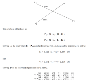
After doing some internet search, I manage to find equations from here that the xx and yy equations solve for the "intersection point of two line segments in 2 dimensions". An image will be linked below.

START IMAGE. Intersection of two lines

END IMAGE.

Q2. I don't understand how he uses the xx and yy equations to solve for a & b?

Q3. I am unsure of what a and b are. My best guess is that they are the bottom row of a projective transformation matrix shown below:

$$ \begin{bmatrix} a_{11} & a_{12} & a_{13} \\ a_{21} & a_{22} & a_{23} \\ a & b & 1 \\ \end{bmatrix} $$

This is because the code sets a = b = 0.0 if we're not doing a projective transform, which should then make it an affine transformation matrix.

Now is where the main loop happens:

for (x=0;x<sx;x++) 
    for (y=0;y<sy;y++) {
        fx = (float)x + 0.5;
        fy = (float)y + 0.5;
        d = a*fx/(float)(*sx)+b*fy/(float)(*sy)+1.0;
        xx = (a+1.0)*fx/d;
        yy = (b+1.0)*fy/d;
        xp = X1 + xx*x12 + yy*x13;
        yp = Y1 + xx*y12 + yy*y13;
    }

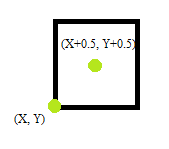
Q4. Why does he add 0.5 to the original x and y coordinate? My best guess is that the code's trying to map the centre of each pixel rather than the edge to the new image:

Pixels

Q5. In

d = a*fx/(float)(*sx)+b*fy/(float)(*sy)+1.0;
xx = (a+1.0)*fx/d;
yy = (b+1.0)*fy/d;

what are they trying to accomplish here? My best guess is that d is the third component of the output homogeneous coordinate:

$$ \begin{bmatrix} xx\\ yy\\ d\\ \end{bmatrix} $$

calculated from the dot product of the third row of the (now normalised) transformation matrix from earlier and the input homogeneous vector:

$$ \begin{bmatrix} \frac{a}{sx} & \frac{b}{sy} & 1 \\ \end{bmatrix} \begin{bmatrix} fx\\ fy\\ 1\\ \end{bmatrix} = a*fx/sx+b*fy/sy+1.0 $$

Then the division

xx = (a+1.0)*fx/d;
yy = (b+1.0)*fy/d;

would just transform the homogeneous coordinates back to Euclidean coordinates, corresponding to the output image pixel location. I noted that if a=b=0.0 (so not projective), then (a+1.0)=(b+1.0)=d=1.0. I'm however not sure about why we have to multiply by (a+1.0) or (b+1.0). But again, I do not know if I'm on the right track or not as I do not have anyone to help me with this code.

Q7. The final operation

xp = X1 + xx*x12 + yy*x13;
yp = Y1 + xx*y12 + yy*y13;

I suppose is literally the dot product of the first two rows of the transformation matrix with the Euclidean coordinates as so:

$$ \begin{bmatrix} x12 & x13 & X_{1} \\ y12 & y13 & Y_{1} \end{bmatrix} \begin{bmatrix} xx\\ yy\\ 1\\ \end{bmatrix} = \begin{bmatrix} xp\\ yp\\ \end{bmatrix} $$

Which brings me to my question, how does this achieve an affine transformation?

I suspect my lack of formal training could be why I'm not understanding how the code models an affine transformation. I'd appreciate some light shed on this piece of code!

Cheers!
$\endgroup$
3
  • $\begingroup$ An affine transformation is is any transformation that preserves points, lines and planes. This can be translation, skewing and rotation - and combinations thereof. $\endgroup$
    – beyond
    Commented Sep 11, 2018 at 8:23
  • $\begingroup$ Hi @beyond, thanks for your input. Are you able to shed some light on the code? $\endgroup$
    – theunseen
    Commented Sep 11, 2018 at 9:00
  • $\begingroup$ To be honest, the code seems a bit elaborate for something as simple as applying an affine transformation to an image. The projection bit I don't get, so an example of input/expected output/actual output would be ideal. $\endgroup$
    – beyond
    Commented Sep 11, 2018 at 12:57

1 Answer 1

2
$\begingroup$

Your understanding of the matrix structure in Q3 is correct. This code just does not construct a matrix explicitly and the matrix multiplication is applied implicitly. I think this part might cause your confusion. Instead of deciphering the code, I would rather derive the transform and compare it with the code.

The affine (6 degrees of freedom) and projective matrix (8 dof) map points to points. So you can build a system of equations for each pair of points in different frames. You will need to solve this system for the components of the matrix (Q1).

Let $M$ be the transform matrix, then

$$ \begin{align} M (0,0,1) &= (X_1,Y_1,1) \\ M (1,0,1) &= (X_2,Y_2,1) \\ M (0,1,1) &= (X_3,Y_3,1) \\ \end{align} $$ Each of above lines gives you two equations. Now you have 6 equations and the affine matrix can be derived. For the projective matrix, we need extra two equations using the point $(X_4,Y_4)$:

$$ \begin{align} H_4 &= M (1,1,1) \\ \frac{H_4}{H_4.z} &= (X_4,Y_4,1) \end{align} $$ Note that I have to divide the homogeneous part for the transformed point.

Solve this linear system you can get an expression for your matrix $M$. Perform $M (f_x,f_y,1)$ you will see how it transforms the point. I believe this solves your Q2, Q3, Q5 and Q7.

For Q4, I think it is just a convention of pixel position and your understanding should be correct.


Appendix: maple code to verify the answer

with(ListTools):
# affine matrix
m:=<m11,m21,0|m12,m22,0|m13,m23,1>;
# Build equations
E:=[convert(m.<0,0,1> - <X1,Y1,1>,list),convert(m.<1,0,1> - <X2,Y2,1>,list), convert(m.<0,1,1> - <X3,Y3,1>,list)];
# E=[[m13 - X1, m23 - Y1, 0], [m11 + m13 - X2, m21 + m23 - Y2, 0],[m12 + m13 - X3, m22 + m23 - Y3, 0]]
# Solve E=0
sol:=eliminate(Flatten(E),indets(m));
# Plug the solution back to m:
subs(sol[1],m);
                           [-X1 + X2    -X1 + X3    X1]
                           [                          ]
                           [-Y1 + Y2    -Y1 + Y3    Y1]
                           [                          ]
                           [   0           0        1 ]


# projective matrix
p:=<m11,m21,a|m12,m22,b|m13,m23,1>;
# Compute transformed points
U0:=p.<0,0,1>;
U1:=p.<1,0,1>;
U2:=p.<1,1,1>;
U2:=p.<0,1,1>;
U3:=p.<1,1,1>;
# Build equations
E:=[convert(U0/U0[3]-<X1,Y1,1>,list),convert(U1/U1[3]-<X2,Y2,1>,list),convert(U2/U2[3]-<X3,Y3,1>,list),convert(U3/U3[3]-<X4,Y4,1>,list)];
# Sove E=0
solp:=eliminate(Flatten(E),indets(p));
# copy their code for xx and yy:
xx:=((X4-X1)*(Y3-Y1)-(Y4-Y1)*(X3-X1))/((X2-X1)*(Y3-Y1)-(Y2-Y1)*(X3-X1));
yy:=((X4-X1)*(Y2-Y1)-(Y4-Y1)*(X2-X1))/((X3-X1)*(Y2-Y1)-(Y3-Y1)*(X2-X1));
# Verify our a and b, compare ours with their expressing using xx and yy
subs(solp[1],a);
subs(solp[1],b);
simplify(subs(solp[1],a)-(yy-1)/(1-xx-yy));
# It is 0 as expected
simplify(subs(solp[1],b)-(xx-1)/(1-xx-yy));
# It is also 0
$\endgroup$

Your Answer

By clicking “Post Your Answer”, you agree to our terms of service and acknowledge you have read our privacy policy.

Not the answer you're looking for? Browse other questions tagged or ask your own question.