My goal in my project is to render a procedural texture for a given mesh based on a predefined camera projection. The way I choose to accomplish it is by creating tex coords based on only the visible triangles for a given projection.
Its important to note that the mesh is unindexed and each vertex is unique to each triangle. After calculating the UV I pass the tex coords, vertices, MVP matrix to a shader program.
In the vertex shader I define the gl_position as the generated tex coords so in the end of the pass i will get a texture that is defined by the tex coords.
layout(location = 0) in vec3 aPos;
layout(location = 1) in vec2 aTexCoord;

out VS_OUT {
vec4 projector;
vec2 uv;
vec2 old_uv;
} vs_out;
void main()
{
gl_Position = vec4(aTexCoord*2.0f - 1.0f, 0.0f, 1.0f);
vs_out.projector = vec4(aPos, 1.0f);
vs_out.uv = aTexCoord;
}
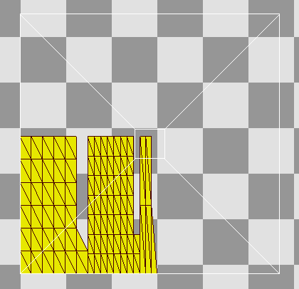
AN example of the output of the vertex shader
Then in the fragment shader, I color the mesh with a simple red color (in the future I hope to project images instead of the red color) :
#version 450
layout(location = 0) out vec4 FragColor;
in VS_OUT{
vec4 projector;
vec2 uv;
} vs_out;
uniform sampler2D shadowMap;
uniform mat4 model;
uniform mat4 projProj;
uniform mat4 projBias;
uniform mat4 projView;
float ShadowCalc(vec4 proj)
{
float closestDepth = texture2DProj(shadowMap, proj).r;
float currentDepth = proj.z / proj.w;
float shadow = currentDepth - 0.00005 > closestDepth ? 0.0 : 1.0;
return shadow;
}
void main()
{
vec4 ndcProj = (projBias * projProj * projView * model * vs_out.projector);
vec2 projUV = (ndcProj.xy / ndcProj.w);
float fDepth = ndcProj.z / ndcProj.w;
vec4 col = vec4(0.0, 0.0, 0.0, 1.0);
if (0.0 < projUV.x && projUV.x < 1.0 && 0.0 < projUV.y && projUV.y < 1.0 && ndcProj.w > 0.0 && ShadowCalc(ndcProj) > 0.5)
{
col = vec4(1.0,0.0,0.0,1.0);
}

FragColor = col;
}
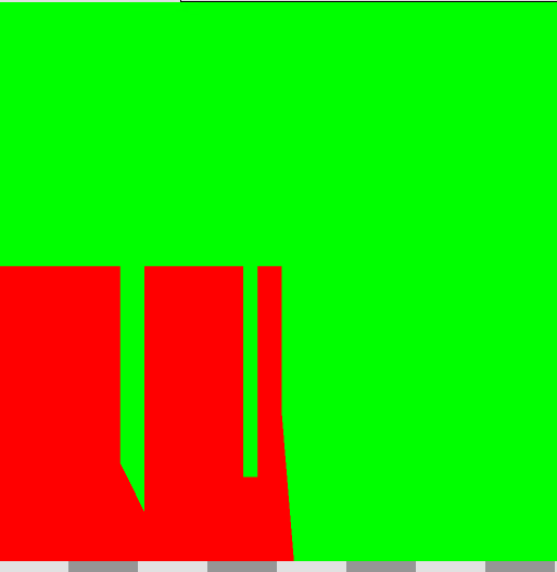
The result after the fragment shader (the texture is cleared with a green color before)
I then display the mesh with the texture using the same tex coords with the following program: Vertex shader:
#version 450
layout(location = 0) in vec3 aPos;
layout(location = 1) in vec2 aTexCoord;
uniform mat4 model;
uniform mat4 projProj;
uniform mat4 projView;
out vec2 texCoordOut;
void main()
{
gl_Position = projProj * projView * model * vec4(aPos, 1.0f);
texCoordOut = aTexCoord;
}
Fragment shader:
#version 450
in vec2 texCoordOut;
out vec4 out_color;
uniform sampler2D unwarp_image;
void main()
{
vec4 color = texture(unwarp_image, texCoordOut.st);
out_color = color;
}
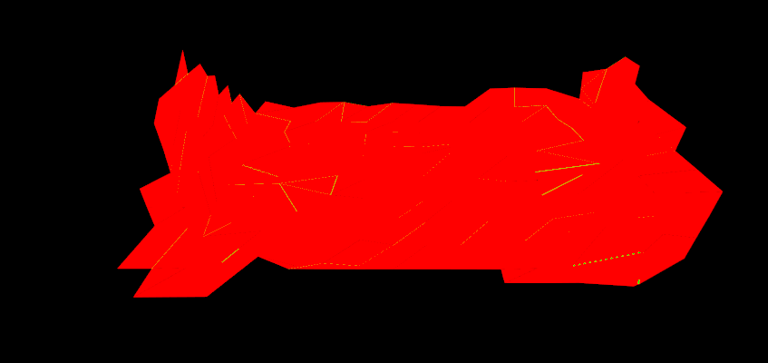
The result:
The mesh rendered with the texture on screen
As you can see, the mesh has these strange wireframe artifacts. I've thought of several solutions such as enabling conservative conservative rasterization but none seem to work. Any ideas on how to get a clean rendering of the mesh with the procedural texture?


