If you are doing a perspective image and your model has implicit intersections then, if you use "linear Z", those intersections will appear in the wrong places.
For example, consider a simple ground plane with a line of telephone poles, receding into the distance, which pierce the ground (and continue below). The implicit intersections will be determined by the interpolated depth values. If those are not interpolated with 1/Z, then when the projected vertices have been computed with perspective, the image will look incorrect.
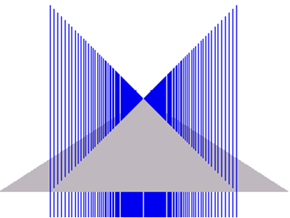
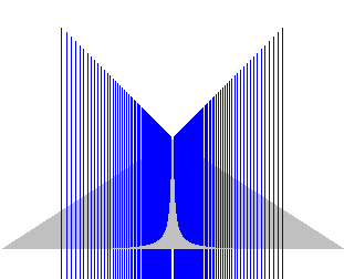
I apologise for the non-aesthetic quality of the following illustrations but I did them back in '97.
The first image shows the required rendering effect. (Note that the blue "pylons" go quite a long distance under the ground plane so are clipped at the bottom of the images)
This second image shows the result of using a non-reciprocal depth buffer: (Apologies for the change of scale - these were copied out of an old MS Word doc and I've no idea what has happened with the scaling.)
As you can see, the results are incorrect.
On another note, are sure you really want a linear Z representation? If you are rendering perspective, surely one wants more precision closer to the camera than at a distance?
Re your later comment:
“if those are not interpolated with 1/Z” that I don’t understand. What interpolation is that?
The first thing to note is that, with a standard perspective projection, straight lines in world space remain straight lines in perspective space. Distances/lengths, however, are not preserved.
For simplicity, let us assume a trivial perspective transform is used to project the vertices, i.e. $$X_{Screen} = \frac{X_{World}}{Z_{World}}$$ $$Y_{Screen} = \frac{Y_{World}}{Z_{World}}$$ We should also compute a reciprocal screen-space depth, e.g. $$Z_{Screen} = \frac{1}{Z_{World}}$$ but a linear Z would in the depth buffer would, to me, implyrequire something like: $$Z_{Screen} = scale*Z_{World}$$ (We can assume here that scale=1)
Let's assume we have a line with world space end points$$ \begin{matrix} \begin{bmatrix} 0 \\ 0 \\ 1 \\ \end{bmatrix} and \begin{bmatrix} 200 \\ 0 \\ 10 \\ \end{bmatrix}\\ \end{matrix} $$ With the perspective mapping these map to screen space coordinates $$ \begin{matrix} \begin{bmatrix} 0 \\ 0 \\ 1 \\ \end{bmatrix} and \begin{bmatrix} 20 \\ 0 \\ 0.1 \\ \end{bmatrix} \end{matrix}$$
The rendering system/hardware will linearly interpolate the screen space z, so at the 1/2 way point of the line, as it appears on-screen, i.e. at pixel (10, 0), we would get a projected (inverse) Z value of 0.55, which corresponds to to a world space Z value value of ~1.818. Given the starting and end Z values, this is about 20% along the length of the line.
If instead, we tried to interpolate using the original Z values, we'd end up with Z corresponding to a world space value of 5.5. As long as nothing intersects, you might be ok (I've not thought about it too thoroughly) but anything with implicit intersections will be incorrect.
What I haven't mentioned is that once you introduce perspective correct texturing (or even perspective correct shading), you must do per-pixel interpolation of 1/w and, additionally, also compute, per pixel, the reciprocal of that interpolated value.

